Bolt greaser unit

a technology of bolts and greasers, which is applied in the direction of lubricating elements, fastening means, coatings, etc., can solve the problems of large amount of time, relatively slow process, and cost over a million dollars for wind generators to manufacture and install on an operational site, and achieve the effect of economic manufacture and mark

Inactive Publication Date: 2006-04-11
TOOMAN NORMAN L
View PDF7 Cites 8 Cited by
  • Summary
  • Abstract
  • Description
  • Claims
  • Application Information

AI Technical Summary

Benefits of technology

[0008]The exposed outer surface of the top end of the anchor bolts then has a film of grease applied thereto that cuts off any oxygen contact with the threads of the anchor bolts. Presently this film of grease is applied manually which is a relatively slow process. When it is kept in mind that approximately 250 of these anchor rods need their top ends greased, the amount of time to accomplish this task is considerable. The bolt greaser unit can accomplish this task at a much faster pace and also in a much shorter accumulated time. A gob of grease is applied to the top end of the anchor bolts by lowering the open bottom end of a grease cartridge over the top of the anchor bolt until a gob of grease is applied thereto. Next the bolt greaser unit is lowered over the top end of the anchor bolt and the cordless power tool is actuated to quickly rotate the bolt greaser unit and spread the grease throughly into the exposed threads of the anchor bolt. This is accomplished in a matter of seconds and the worker can go from one anchor bolt to the next until he has completed the entire periphery of the tower base.
[0009]The bolt greaser unit has a cylindrical housing having a circular base member secured to its bottom end and a removable circular cap member. The circular base member has a central aperture whose width is greater than the diameter of any anchor bolt to be greased by the bolt greaser unit. The diameter of the central aperture would preferably be less than the diameter of the nuts that tighten down the anchor bolts so that the base member would rest on the upper surface of the nut. The top surface of the circular base member has threaded bore holes for receiving the threaded bottom ends of a plurality of rod members extending upwardly therefrom. Each rod member has a brush member having a bore hole that allows them to be telescopically slid over the top end of the rod members down into the chamber of the tubular housing. The top ends of the rod members are also externally threaded and these pass through apertures in the circular cap member. Nuts are fastened on the top ends of these rod members to hold the circular cap member in position. The width of the brush members and the spacing therebetween in the interior of the tubular housing is such that the top end of the anchor bolt would have its external threads pushed directly into contact with the surface of the brush members and the grease would also be throughly applied to the threads. The rotation of the bolt greaser unit quickly and throughly greases the top end of the exposed anchor bolts. Next the anchor bolt caps are slid over the top end of the anchor bolts. When properly aligned and centered, the bolt caps are easily pounded down on to the top of the nut and frictionally held in place. The width of the interior of the anchor bolt reception portion of the anchor bolt caps is only slightly larger than the diameter of the anchor bolt. This eliminates the possibility of the anchor bolt cap being rocked back and forth either by the stress produced upon it when the generator is operating or by individuals attempting to rock the anchor bolts caps off.

Problems solved by technology

Wind generators generally cost over a million dollars to manufacture and install them on an operational site.
Presently this film of grease is applied manually which is a relatively slow process.
When it is kept in mind that approximately 250 of these anchor rods need their top ends greased, the amount of time to accomplish this task is considerable.

Method used


Image

  • Bolt greaser unit
  • Bolt greaser unit
  • Bolt greaser unit

Examples


Embodiment Construction

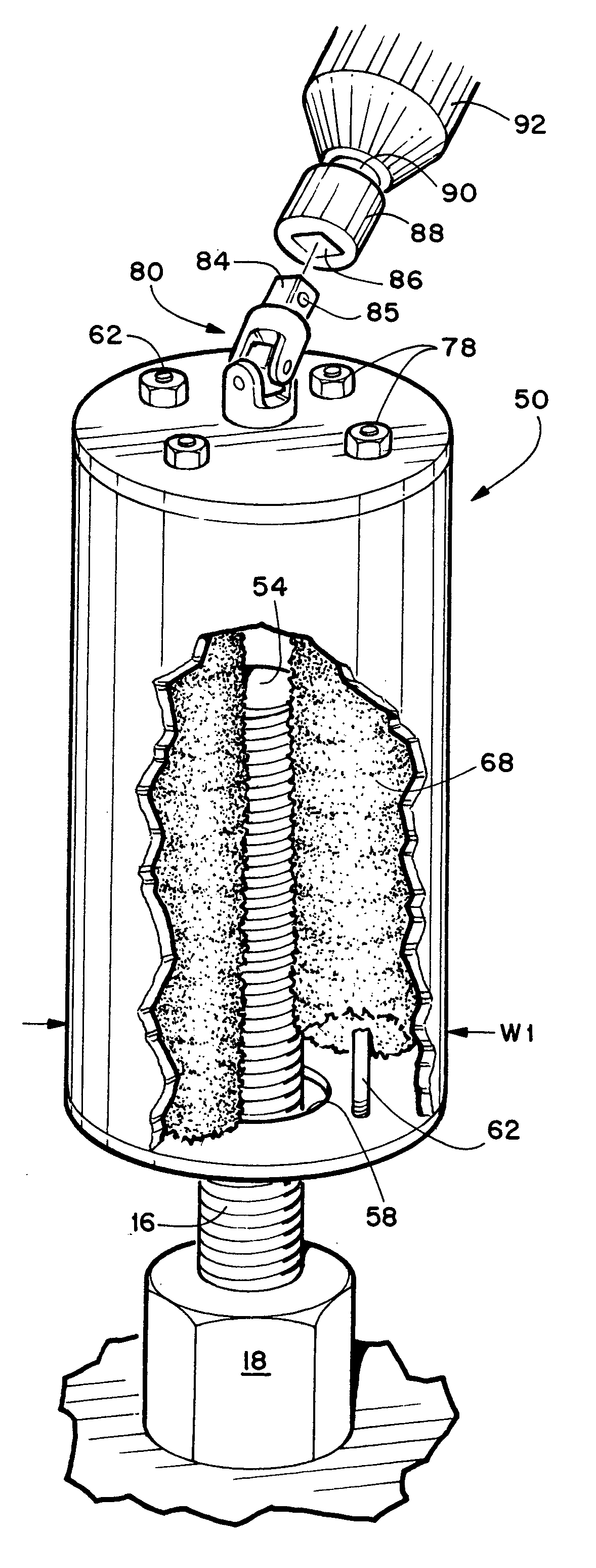
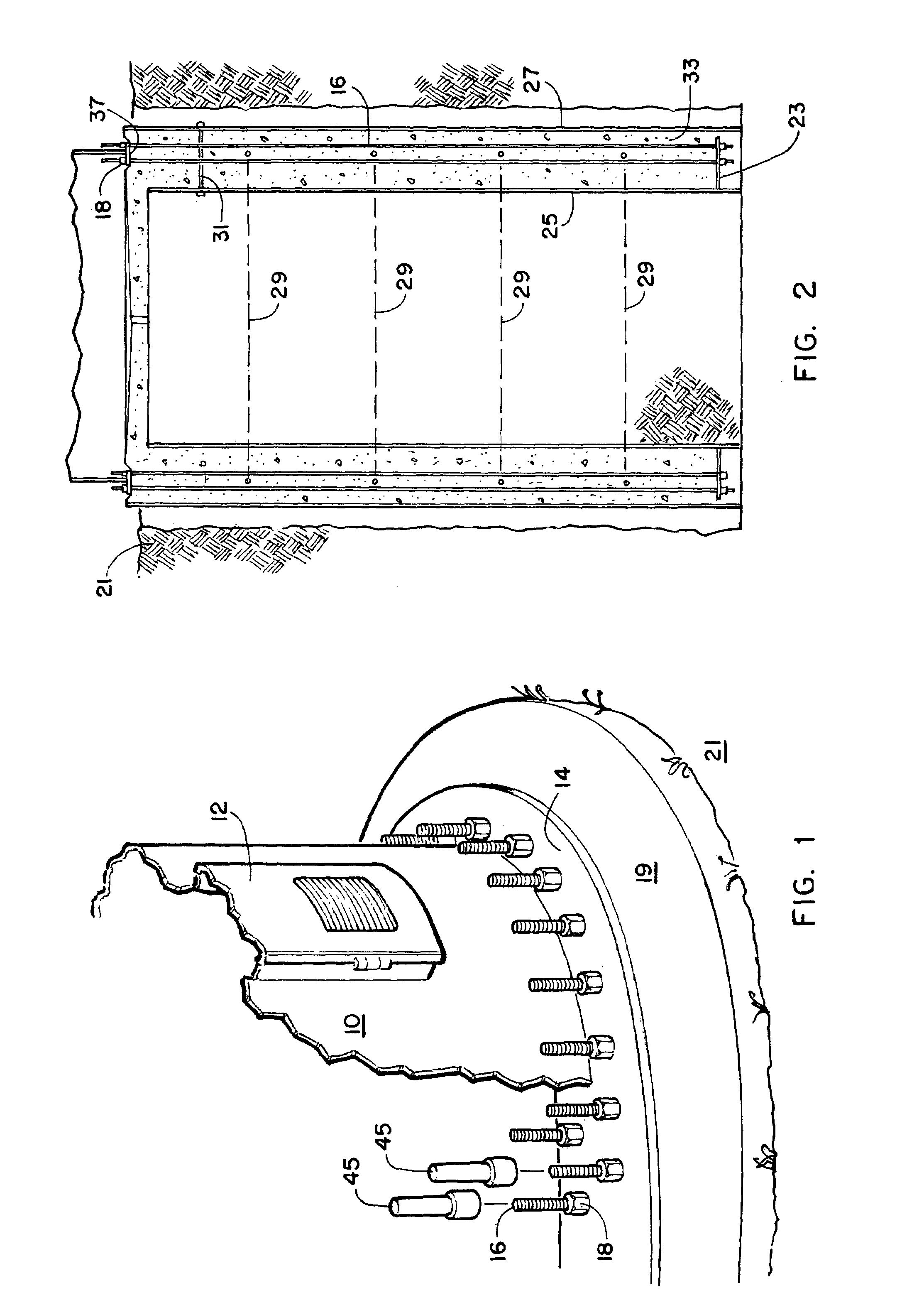
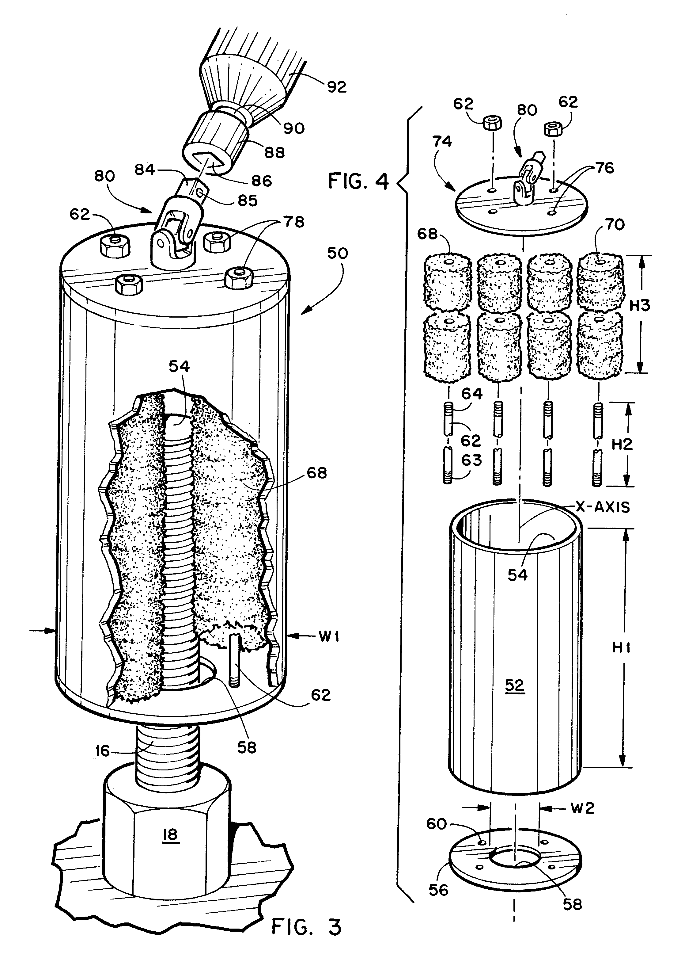
[0017]The invention will now be described by referring to FIGS. 1–2 of the drawings. FIG. 1 shows the bottom end of the tower base 10 of a wind generator. The tower base is normally 200 feet high and the wind generator has multiple blades (not shown) that are rotated by the wind. A door 12 gives access to the interior of the tower base. An outer annular flange 14 is formed on the bottom end of tower base 10 and a similar inner annular flange (not shown) would be on the interior of the tower base 10. The top ends of anchor bolts 16 extend at least 10 inches above the top surface of flange 14 and each has a nut 18 threaded thereon. A concrete walk 19 extends around the perimeter of tower base 10. The base foundation 20 is not seen and it is covered by dirt 21.

[0018]FIG. 2 is a schematic side elevation view of base foundation 20. It is formed on site in a hole approximately 30 feet deep and about 10–15 feet in diameter. A metal embedment ring 23 is placed in the base foundation hole sp...


PUM


Abstract

A bolt greaser unit for lubricating the exposed top ends of anchor bolts that secure the base tower of wind generators to the foundation that is formed in the ground. The bolt greaser unit has a vertically oriented tubular housing having a base member secured to its bottom end and a circular cap member detachably secured to its top end. The interior chamber of the tubular housing has a plurality of vertically oriented rod members having their bottom ends screwed into the top surface of the base member. Each rod member has a brush member telescopically received thereon. The top end of the rod members pass through apertures in the circular cap member and are secured in position by nuts. A universal joint structure is fixedly secured to the top surface of the cap member and it has a four sided shank portion extending upwardly that is telescopically received in the bore hole of a socket mounted on the drive shaft of a cordless power tool that would be used to rotate the bolt greaser unit. The base member has a central aperture having a width greater than the diameter of the anchor bolts over which the bolt greaser unit is lowered. A gob grease would be placed on the top end of the anchor bolts prior to insertion into the bottom end of the bolt greaser unit and when the drive shaft of the power tool rotates, the grease would be throughly spread into the grooves of the threads of the anchor bolts.

Description

BACKGROUND OF THE INVENTION[0001]The invention relates to wind generators having propellers or blades that are rotated by the force of the wind to produce electricity. More specifically, the invention relates to the exposed top ends of the anchor bolts that secure the tower base of the wind generator to the foundation that is formed in the ground. Prior to installing bolt caps over the exposed top ends of the anchor bolts, grease must be applied to the exposed external threads of the anchor bolts. The bolt greaser unit accomplishes this task both quickly and economically.[0002]Presently there are numerous wind generators in existence that have a tower base 200 feet or higher. These wind generators have blades or propellers up to ninety feet or longer. There may be as many as 240 or more anchor bolts used to secure the tower base to the foundation. The foundation itself may be in the order of thirty feet deep and these anchor bolts may be in the order of thirty feet long. During the ...

Claims


Application Information

Patent Timeline
Patent Type & Authority Patents(United States)
IPC IPC(8): F16N7/00
CPCF16N11/00
Inventor TOOMAN, NORMAN L.
Owner TOOMAN NORMAN L
Why Eureka
Try Eureka