Torque releasing device

a technology of torque releasing device and torque release, which is applied in the direction of interengaging clutches, hose connections, slip couplings, etc., can solve the problems of inability to secure the torque release, fretting between the balls, etc., and achieve the effect of preventing the occurrence of fretting

Inactive Publication Date: 2006-04-11
KOYO SEIKO CO LTD
View PDF8 Cites 8 Cited by
  • Summary
  • Abstract
  • Description
  • Claims
  • Application Information

AI Technical Summary

Benefits of technology

[0008]It is, therefore, an object of the present invention to provide a torque releasing device which is designed t

Problems solved by technology

Where the bearing is the deep-groove ball bearing, however, fretting occurs between the balls and raceway surfaces each of the races during the normal operation (in a state where the races and the balls do not perform the relative motion).
Where the bearing sustaining th

Method used


Image

  • Torque releasing device
  • Torque releasing device

Examples


Embodiment Construction

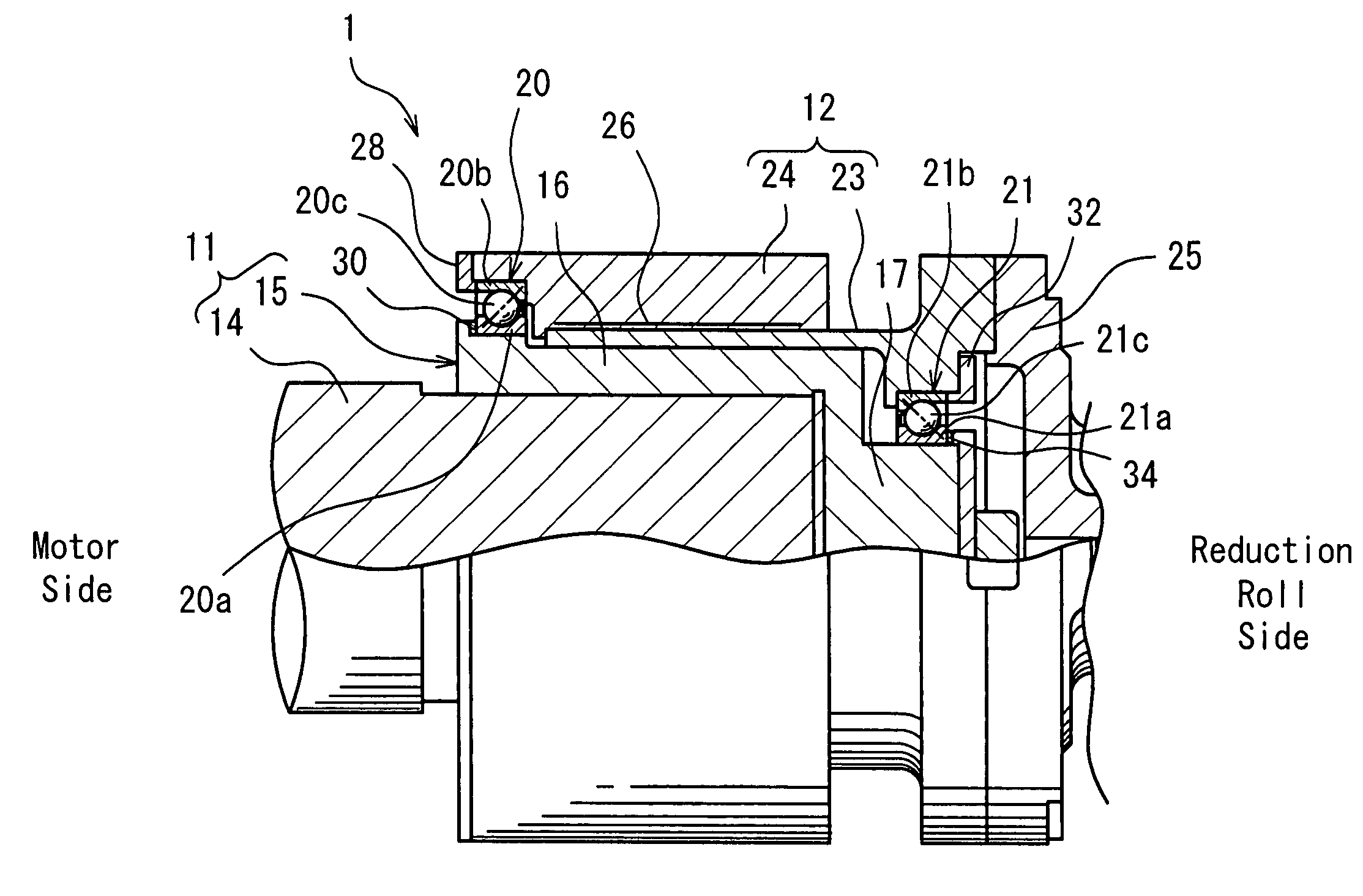
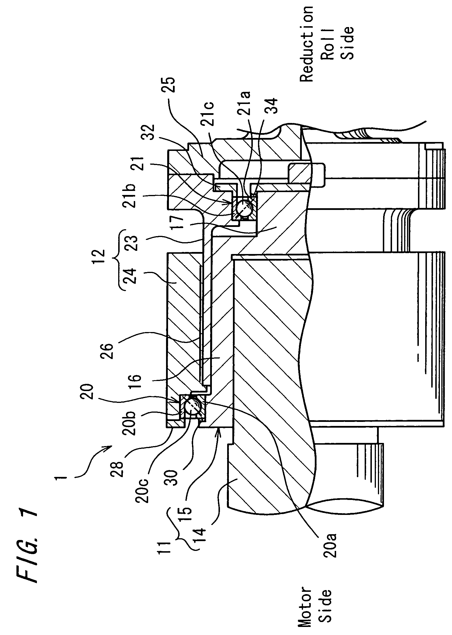
[0015]A preferred embodiment of the present invention will hereinbelow be described with reference to the accompanying drawing. FIG. 1 shows a torque releasing device 1 according to an embodiment of the present invention. The torque releasing device 1 is used in a power transmission system for a rolling mill and is disposed between a reduction roll (not shown) and a motor (not shown) for driving the reduction roll.

[0016]The torque releasing device 1 transmits torque from the motor to the reduction roll during normal operation. However, in the event of trouble on a reduction roll side, such as locking or abnormal torque (excessive torque), the device releases the torque so as to disable the transmission of the torque from the motor to the reduction roll and hence, the motor idles.

[0017]The torque releasing device 1 includes a first member 11 connected to the motor; and a second member 12 connected to the reduction roll via an unillustrated universal joint. The first member 11 is fitt...


PUM


Abstract

In a torque releasing device, a bearing is composed of an angular contact ball bearing, raceway surfaces of which are applied with a pre-load in order that the occurrence of fretting at the bearing during torque transmission may be prevented. Thus is ensured that the torque is securely released.

Description

FIELD OF THE INVENTION[0001]The present invention relates to a torque releasing device.DESCRIPTION OF THE PRIOR ART[0002]As a conventional torque releasing device, there is known one disclosed in Japanese Unexamined Patent Publication No.5-87149. The torque releasing device includes a shaft member; and a cylinder member having a hydraulic oil path operative to press an inner circumferential face thereof against an outer circumferential face of the shaft member. Normally, the cylinder member is engaged with the shaft member by means of pressure oil supplied to the hydraulic oil path, so that torque may be transmitted between the shaft member and the cylinder member.[0003]Torque releasing takes place when the shaft member or the cylinder member is subjected to load in excess of a predetermined value. When the load above the predetermined value causes the cylinder member to slip at its inner circumferential face, the pressure oil in the hydraulic oil path is discharged outside so as to...

Claims


Application Information

Patent Timeline
IPC IPC(8): F16D1/06F16C25/06F16C19/16F16C19/54F16C35/073F16D1/091F16D7/02
CPCF16D7/021Y10T403/13F16C19/163F16C19/548F16C25/06F16C2361/41F16C2229/00F16D1/06
Inventor NAGAYAMA, AKIHIDENUMADA, YOUICHI
Owner KOYO SEIKO CO LTD
Why Eureka
Try Eureka