Machine-mounted thread carousel for home sewing and embroidery machines

a technology for sewing machines and thread carousels, which is applied in the direction of spool pin assemblies, thin material handling, textiles and papermaking, etc. it can solve the problems of increasing the thread path, entanglement of the end still attached to the spool, and entanglement of other such spool threads, so as to achieve the effect of easing the change of threads and ensuring the effect of uniformity

Inactive Publication Date: 2006-04-11
MORKOVSKY HENRY
View PDF14 Cites 6 Cited by
  • Summary
  • Abstract
  • Description
  • Claims
  • Application Information

AI Technical Summary

Benefits of technology

[0009]This invention is a combination spool carrier and thread feeding device for conventional and cross-wound thread alike that installs on a sewing and/or embroidery machine without tools and without modifying the machine in any way. It is light, portable, and self-supporting when dismounted, thereby enabling it to serve as a carrier of selected threads from the thread cabinet to the machine. It can be made of any material such as wood, plastic, and/or metal with equal effectiveness and can incorporate any reasonable number of spools within the parameters of spool size and machine physical characteristics. It provides the shortes

Problems solved by technology

Many of these machines incorporate diagrams or instructions on the inside of the cover and the covers frequently not easily removable, thereby requiring thread stands residing behind the machine to have very tall thread guides in order for the thread coming from the stand to clear the cover.
If snipped at the machine's internal thread path entry point, the thread is not wasted but the end still attached to the spool risks entanglement with other such snipped threads.
There are also thread stands that fasten to the machine but still but behind it, thus imparting the same or similar problems for the operator.
Moving the thread stand to the side of the machine does not solve this problem but increases the thread path and consumes the already small table area normally crowded with pins, scissors, and other sewing accoutrements.
As with Hrobar, U.S. Pat. No. 5,626,302, and Holder, U.S. Pat. No. 6,328,254, devices have been made to adapt non-standard or commercial spools to the vertical spindle of the home s

Method used


Image

  • Machine-mounted thread carousel for home sewing and embroidery machines
  • Machine-mounted thread carousel for home sewing and embroidery machines
  • Machine-mounted thread carousel for home sewing and embroidery machines

Examples


Embodiment Construction

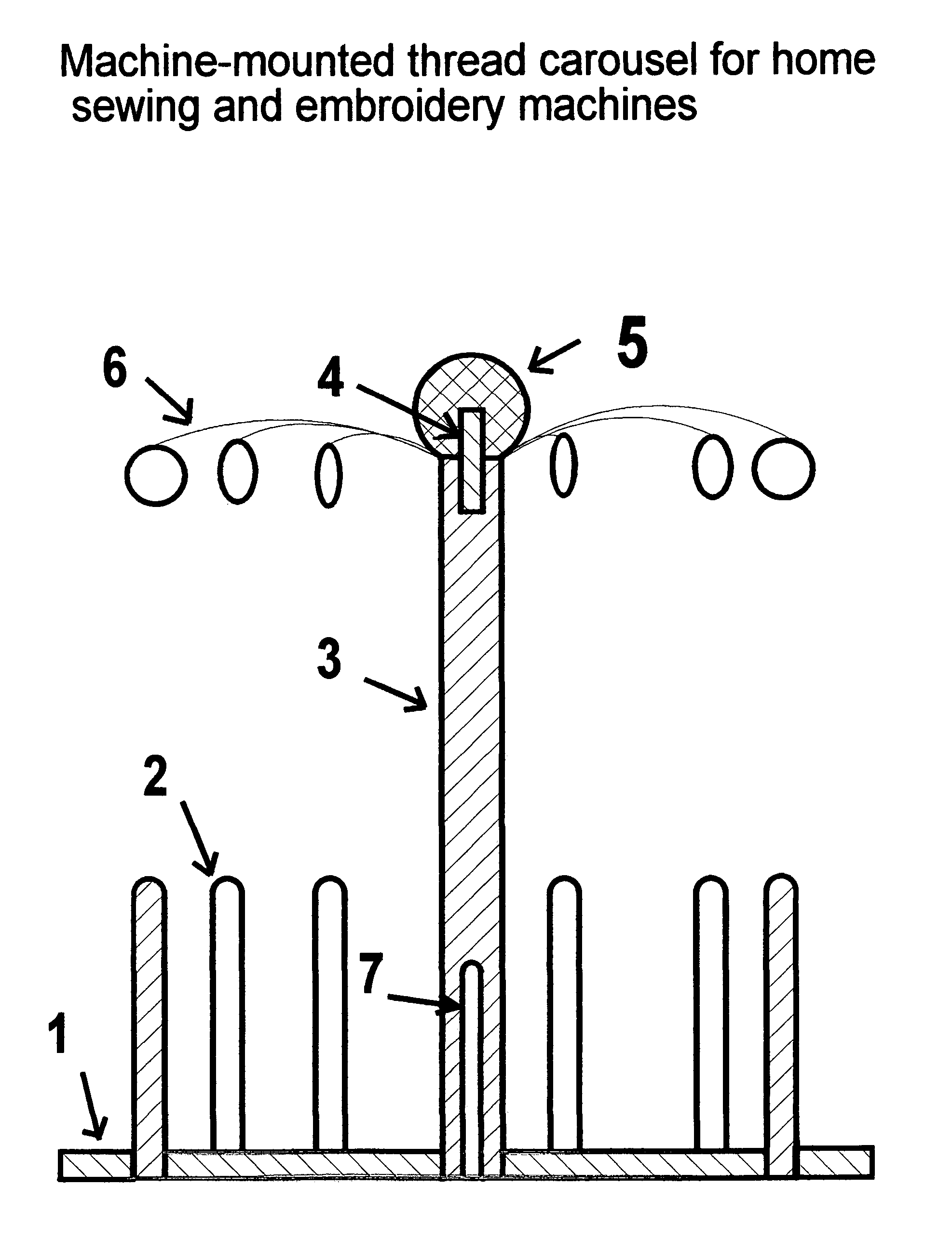
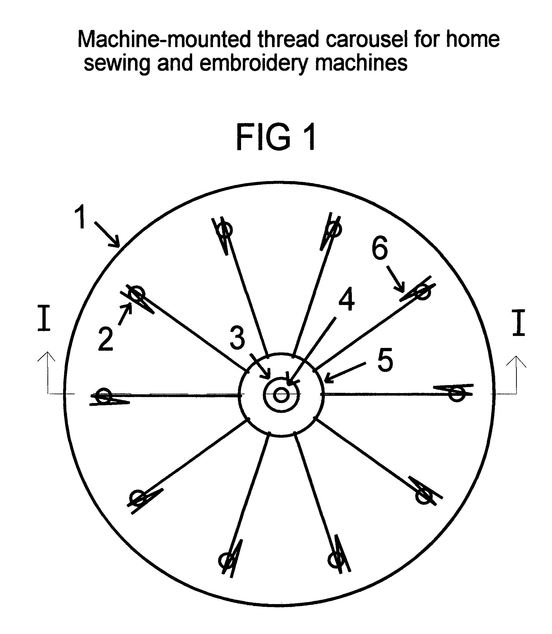
[0014]In FIG. 1, the dimension from the outer periphery of disk 1 to the center of spindles 2 is half the diameter of the spools the carousel is designed to carry. The spacing of adjacent spindles 2 is at least the full diameter of the spools to be carried. Lifting ball 5 can be any size so long as it covers the interface between center dowel 3 and wire guides 6 (under ball 5).

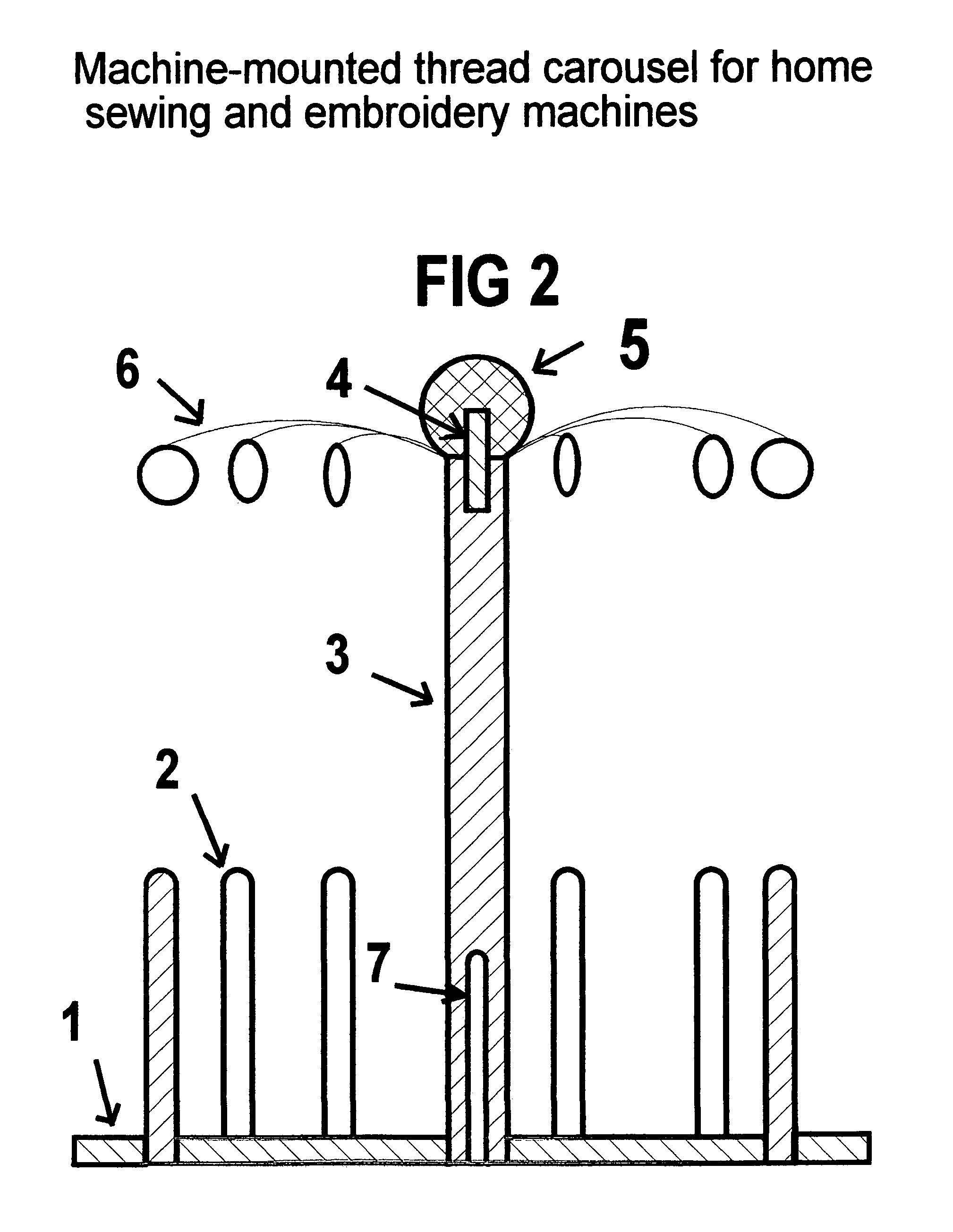
[0015]In FIG. 2, disk 1 of plywood or solid wood, whose outside diameter is determined by the space limitations, if any, of the intended machine is drilled to accept the number and pattern of spindles 2 as defined in FIG. 1 description. Absent machine limitations, disk 1 is sized for any number and size of spools desired. The center of disk 1 is drilled to accept dowel 3, whose height is defined by the clearance required to insert the intended size of spools between the top of spindles 2 and the bottom of guides 6. The top end of dowel 3 is notched radially for each intended guide 6. A hole is drilled ½″ deep ...


PUM


Abstract

This invention is a device for transporting, holding and feeding a plurality of spools of level-wound or cross-wound thread on a home sewing and/or embroidery machine. This device fits over the vertical spindle of the machine if so equipped, or over a spindle devised for the intended machine so as to provide the same function if not so equipped. It consists of a disk with a flat base, free to rotate about its vertical axis, with provisions for accepting spools of thread of various standard sizes. It can be made of any material suitable for the purpose and embodies a thread guide for each spool when used to feed cross-wound thread. It also embodies a knob, pin, ring, or other feature to enable it to be installed/removed from the machine manually without tools.

Description

BACKGROUND OF THE INVENTION[0001](1) Field of the Invention[0002]This invention relates to home machine sewing and embroidery[0003](2) Description of Related Art[0004]Home sewing machines have always been equipped with a vertical spindle to handle spools of level-wound thread. Such spools commonly rotate when in use, thus feeding thread radially. With the advent of the home embroidery and combination sewing / embroidery machines, cross-wound thread has come to the fore. Spools of cross-wound thread do not commonly rotate when in use, and thread is fed axially. It is now the norm on current embroidery-only machines for the primary spindle(s) to be horizontal and on sewing / embroidery machines for an ancillary spindle to be provided for use with level-wound thread. Also, in these machines the bobbin-winder spindle is mounted vertically on the top of the machine, and often the ancillary spindle is merely pushed over the bobbin-winder spindle. Thus, all machines have or can be provided wit...

Claims


Application Information

Patent Timeline
IPC IPC(8): B65H16/02
CPCD05B43/00
Inventor MORKOVSKY, HENRY
Owner MORKOVSKY HENRY
Why Eureka
Try Eureka