Pull type swage fasteners with removable mandrel

Inactive Publication Date: 2006-04-11
HUCK INT INC
View PDF38 Cites 18 Cited by
  • Summary
  • Abstract
  • Description
  • Claims
  • Application Information

AI Technical Summary

Benefits of technology

[0007]In the present invention a removable and reusable mandrel is provided to be threadably secured in a pull cavity at the end of the pin shank and be gripped by the installation tool for applying the relative axial pulling force for s

Problems solved by technology

This portion of the pin shank will have less resistance to compressive loading as the collar is swaged therein and could result in distortion and/or jamming of the threaded portion of the mandr

Method used


Image

  • Pull type swage fasteners with removable mandrel
  • Pull type swage fasteners with removable mandrel
  • Pull type swage fasteners with removable mandrel

Examples


Example

[0034]The following description of the preferred embodiment(s) is merely exemplary in nature and is in no way intended to limit the invention, its application, or uses.

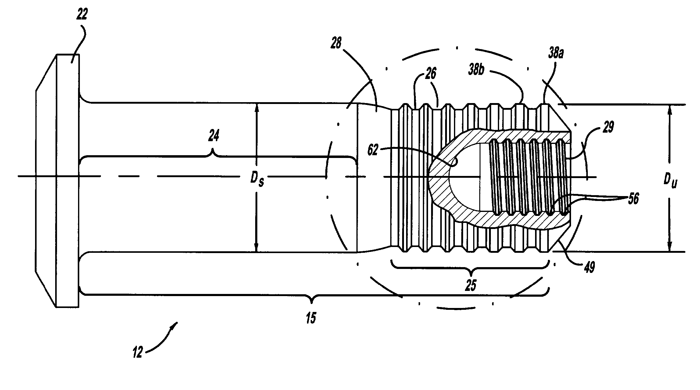
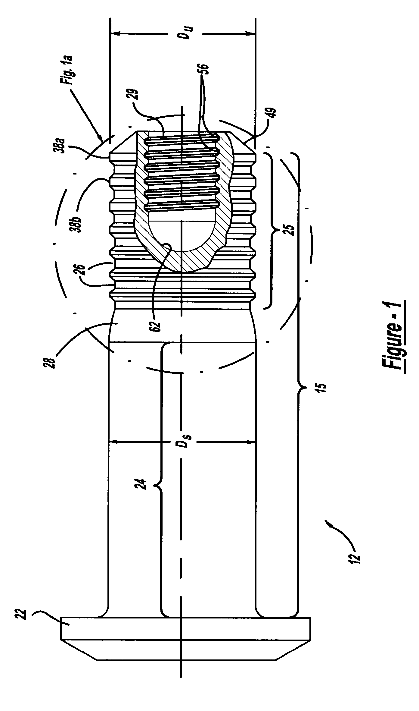
[0035]Looking now to FIGS. 1–5, a pull type swage fastener 10 is shown (see FIG. 5) and includes a pin member 12 and tubular collar 14. Pin member 12 has an elongated shank 15 which is adapted to extend through aligned openings or bores 16 and 17 in a pair of workpieces 18 and 20, respectively, to be secured together. See FIGS. 1 and 5. An enlarged protruding head 22 at one end of the shank 15 engages the back side surface 23 of workpiece 18. The pin shank 15 has a straight, smooth cylindrical shank portion 24 adjacent the head 22 which is adapted to be received within the aligned bores 16 and 17. It should be understood that in some installations the bores 16 and 17 can be made of a size relative to the straight shank portion 24 to provide a desired interference fit or a clearance fit. Following the straight shank po...


PUM

PropertyMeasurementUnit
Fractionaaaaaaaaaa
Fractionaaaaaaaaaa
Fractionaaaaaaaaaa

Abstract

A pull type swage fastener including a pin and a collar adapted to be swaged into a locking portion on the pin shank and with a removable mandrel being threadably securable in a pull cavity at the end of the pin shank and with the mandrel adapted to be gripped by an installation tool for applying a relative axial force between the pin and collar to swage the collar into the locking portion with the mandrel being releasable from the tool and removable from the pull cavity.

Description

FIELD OF THE INVENTION[0001]The present invention relates to pull type swage fasteners in which a collar is swaged into lock grooves on a pin in response to a relative axial force between the pin and collar.BACKGROUND OF THE INVENTION[0002]The present invention relates to a fastening system for pull type swage fasteners including a pin and a collar with the collar adapted to be swaged into the pin with a mandrel removably secured in the shank of the pin and adapted to be gripped by an installation tool for applying the required relative axial pulling force between the pin and collar for swaging the collar.[0003]The present invention relates to two-piece swage type fasteners or lockbolts generally of the type illustrated in U.S. Pat. No. 2,531,048 to L. Huck, issued Nov. 21, 1950, and U.S. Pat. No. 3,215,024 to Brilmyer et al issued Nov. 2, 1965; there are numerous other variations of swage type fasteners such as U.S. Pat. No. 3,915,053 to J. Ruhl, issued Oct. 28, 1975, U.S. Pat. No....

Claims


Application Information

Patent Timeline
IPC IPC(8): F16B19/05F16B4/00B21D39/04B21J15/02B21J15/36
CPCB21J15/022F16B19/05B21J15/365Y10S411/916
Inventor MONSERRATT, ERNESTPARKER, JR., LLOYD
Owner HUCK INT INC
Why Eureka
Try Eureka