Vascular access device

a technology for access devices and arteries, applied in medical science, surgery, other medical devices, etc., can solve the problems that none of these devices has the ease and safety of use that physicians would prefer, and achieve the effects of reducing the number of steps, reducing infection, and simplifying access

Active Publication Date: 2006-04-11
YALE UNIV
View PDF39 Cites 323 Cited by
  • Summary
  • Abstract
  • Description
  • Claims
  • Application Information

AI Technical Summary

Benefits of technology

[0016]The present invention has several advantages, the first of which is its efficiency. Instead of the current multi-step access method with an exchange of guidewires and sheaths, this invention reduces the number of steps and simplifies access. Another advantage is safety. After a vessel is accessed, the guidewire can be left in to protect the needle tip. The needle, dilator and guidewire can be removed together after the sheath is in place. If no additional access is needed in the same procedure, the needle can be bent for added safety. This is contrary to the current technique where the unprotected bloody needle is removed from the guidewire after vascular access is gained. Alternatively, the guidewire can be left in place to provide further access through the sheath and the dilator distal member protects the distal tip of the needle and ultimately the user. Another advantage is the reduction of infection. By minimizing the number of guidewires and sheaths necessary to obtain vascular access, the opportunities for inadvertent contamination are decreased. A further advantage is that under non-hospital or field conditions, use of the invention will decrease the possibility of infection due to a non-sterile environment. A yet further advantage is the added stiffness of the system. The added stiffness provided by the needle is enabling advancement of the system without multiple dilatatio...

Problems solved by technology

However, none of these devices has the ease and safety of use that physicians would prefer, and there is thus a need for an ...

Method used


Image

  • Vascular access device
  • Vascular access device
  • Vascular access device

Examples


Embodiment Construction

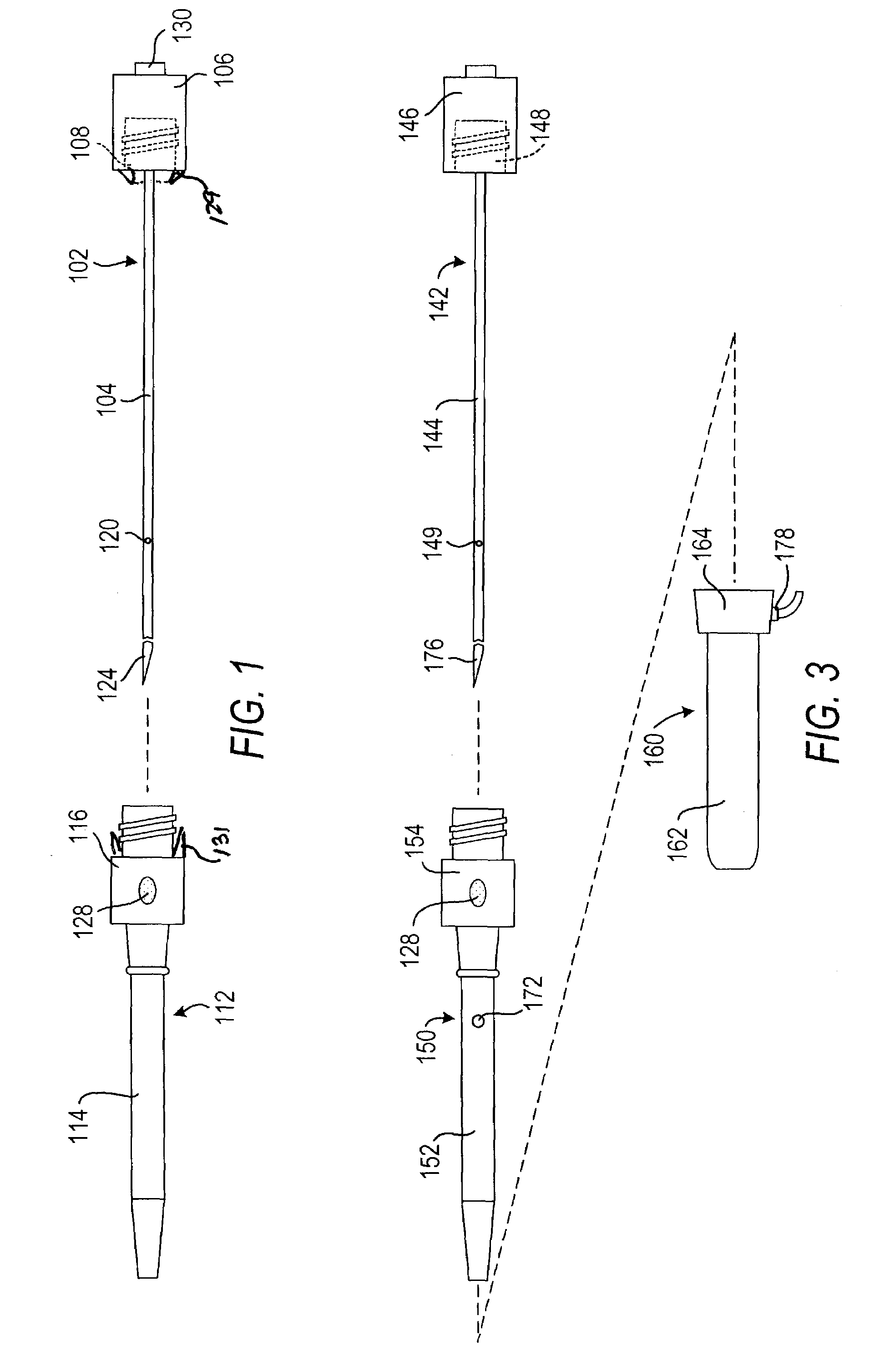
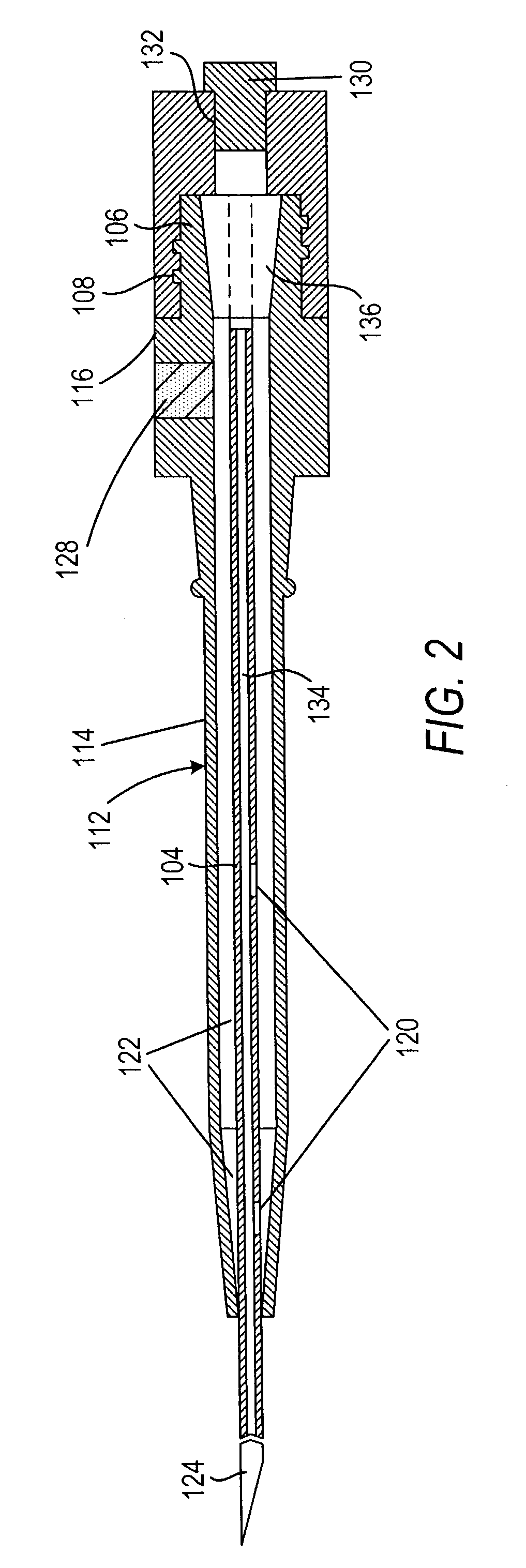
[0030]The invention can perhaps be better appreciated from the drawings. In FIGS. 1 and 2 a needle section 102 comprises a needle 104 and a proximal portion 106 with a twist lock member 108, and a dilator section 112 comprises a dilator 114 and a hub 116. In a preferred embodiment of the invention, needle 104 has one or more openings 120. Dilator 114 is preferably clear, semi-opaque, or translucent so that when blood flows into needle 104 and then through an opening 120 either (1) into an annular space 122 between needle 104 and dilator 114 or (2) into or through spaces (not shown) in dilator 114, the physician can see the blood. This will indicate to the physician that the distal end 124 of needle 104 has punctured a blood vessel (not shown).

[0031]As can be seen in FIG. 2, dilator hub 116 releasably engages needle proximal section 106. Here, dilator hub 116 comprises a conical recess 117 that receives a conical member 119 forming a part of needle proximal section 106. Needle proxim...


PUM


Abstract

A vascular access system comprises a needle having a distal tip and a proximal fitting section and a dilator having a solid distal section connected to a solid proximal section and an annular recess therebetween, the dilator having a passageway so that the dilator is coaxially positioned around the needle. The needle has at least one opening positioned proximal to its distal tip so that, when the distal end of the needle enters a blood vessel, blood enters the annular recess to show the operator that access has been achieved. Optionally, a sheath having a distal tip, a proximal fitting section, and a lumen sufficient to coaxially fit over the dilator.

Description

CROSS-REFERENCE TO RELATED APPLICATION[0001]This application is based upon U.S. provisional patent application Ser. No. 60 / 343,814, filed Dec. 26, 2001.FIELD OF THE INVENTION[0002]This invention is directed to vascular access. More particularly, this invention is directed to a vascular access device that is easier, safer, and faster to use than prior such devices.BACKGROUND OF THE INVENTION[0003]A preferred non-surgical method for inserting a catheter or vascular sheath into a blood vessel involves the use of the Seldinger technique, which includes an access needle that is inserted into a patient's blood vessel. A guidewire is inserted through the needle and into the vessel. The needle is removed, and a dilator and sheath combination are then inserted over the guidewire. The dilator and sheath combination is then inserted a short distance through the tissue into the vessel, after which the dilator is removed and discarded.[0004]The catheter is then inserted through the sheath into t...

Claims


Application Information

Patent Timeline
IPC IPC(8): A61M5/178A61M25/00A61B17/32A61MA61M25/06A61M25/08A61M29/00
CPCA61M25/0606A61M25/0662A61M25/0693A61M2025/0687A61M29/00
Inventor TAL, MICHAEL
Owner YALE UNIV
Why Eureka
Try Eureka