
Surgical fixation system and related methods

a technology of fixation system and surgical fixation, which is applied in the field of surgical fixation, can solve the problems of spinal fixation plate use, screw used to fix spinal fixation plate to the vertebral body having a tendency to back out of the plate, damage or impairment of the organ

Inactive Publication Date: 2006-04-11
NUVASIVE
View PDF6 Cites 175 Cited by
  • Summary
  • Abstract
  • Description
  • Claims
  • Application Information

AI Technical Summary

Benefits of technology

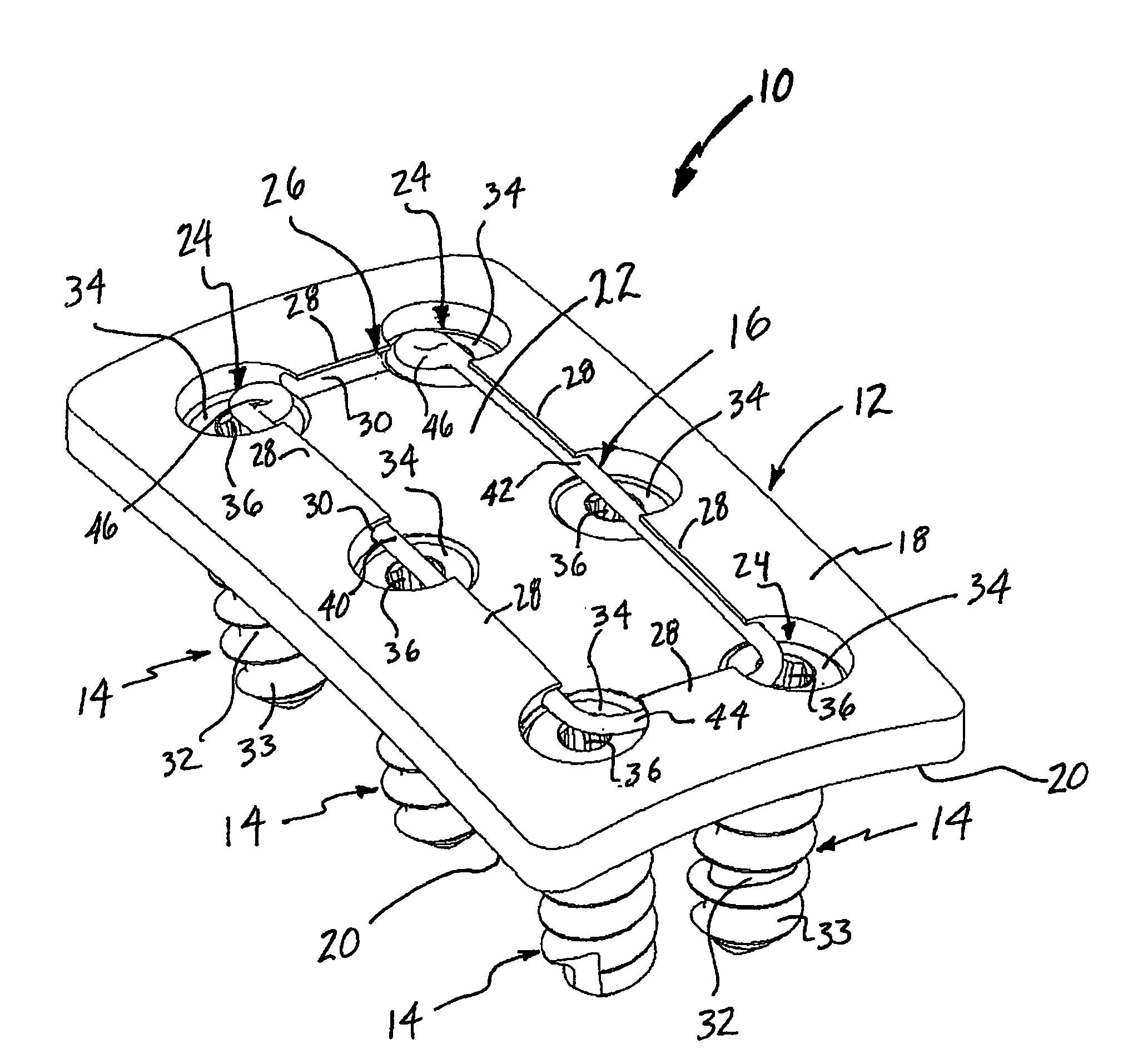
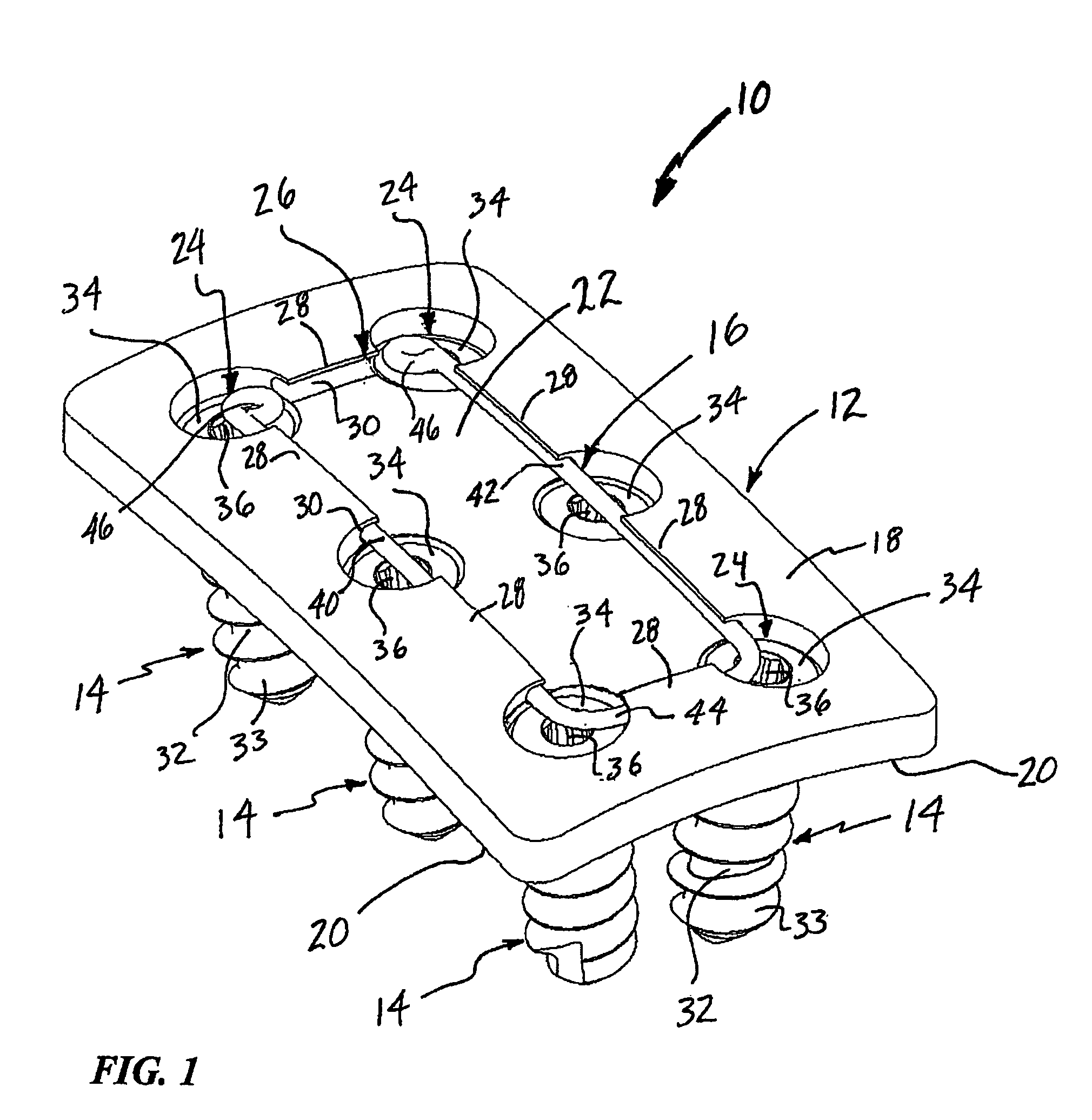
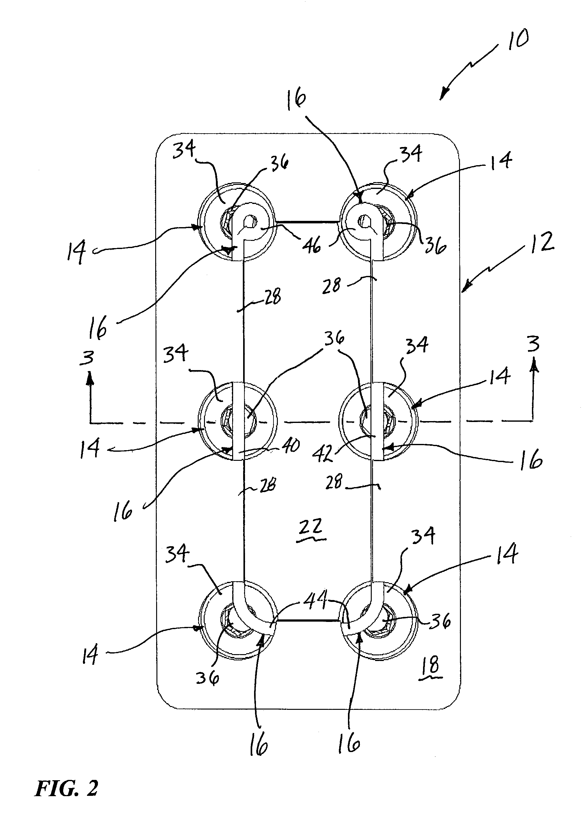
[0009]According to one broad aspect of the present invention, the present invention accomplishes this goal by providing a surgical fixation system including a plate, at least one fastener, and a retainer. The plate has at least one fastener-receiving aperture and at least one retainer-receiving aperture. The fastener-receiving aperture extends between an upper surface and a lower surface of the plate. The retainer-receiving aperture has a periphery defined by a plurality of tab members extending from the upper surface. The fastener has an anchor region and a head region. The anchor region is dimensioned to be passed through the fastener-receiving aperture for introduction into a surgical target site, and the head region is dimensioned to be received at least partially within the fastener-receiving aperture. The retainer is dimensioned to be introduced into the retainer-receiving aperture to overlap at least a portion of the head region of the fastener and thereby prevent the fastener from backing out of the fastener-receiving aperture.

Problems solved by technology

A challenge exists in the use of spinal fixation plates, however, in that the screws employed to fix the spinal fixation plate to the vertebral bodies have a tendency to back out from the plate over time.
More specifically, such backing out may cause the screws to come into unwanted contact with the esophagus, which may lead to damage or impairment to that organ.
Another problem is that, with the screws backed out (partially or fully), the mechanical properties of the overall construct will become compromised, which may lead to a loss in the height of the intervertebral space height and thereby cause pain to the patient.
Unfortunately, both types of prior art systems have various drawbacks or imperfections.
The first type (with a plurality of parts to engage the head of the screw within the through bore) can be challenging due to the plurality of parts and associated instrumentation, which may disadvantageously increase surgical time.
The second type (covering the head of the screw) can similarly be time consuming and challenging based on the need for additional instrumentation to place the cover.
Both types of systems may be more costly based on the need for additional instrumentation above and beyond the screwdriver instrument.

Method used


Image

  • Surgical fixation system and related methods
  • Surgical fixation system and related methods
  • Surgical fixation system and related methods

Examples


Embodiment Construction

[0022]Illustrative embodiments of the invention are described below. In the interest of clarity, not all features of an actual implementation are described in this specification. It will of course be appreciated that in the development of any such actual embodiment, numerous implementation-specific decisions must be made to achieve the developers' specific goals, such as compliance with system-related and business-related constraints, which will vary from one implementation to another. Moreover, it will be appreciated that such a development effort might be complex and time-consuming, but would nevertheless be a routine undertaking for those of ordinary skill in the art having the benefit of this disclosure. The surgical fixation plate disclosed herein boasts a variety of inventive features and components that warrant patent protection, both individually and in combination.

[0023]This invention improves upon the prior art by providing a surgical fixation system including a surgical f...


PUM


Abstract

A surgical fixation system including a surgical fixation plate, a plurality of fasteners, and a retainer having an improved mechanism to prevent the back out of screws employed in securing a surgical fixation plate to an intended orthopedic location.

Description

CROSS-REFERENCE TO RELATED APPLICATION[0001]This application claims the benefit of the filing date under 35 USC 119(e) of United States Provisional Application entitled “Anterior Cervical Plate,” Ser. No. 60 / 384,966 filed Jun. 4, 2002, the entire contents of which is fully incorporated herein by reference.BACKGROUND OF THE INVENTION[0002]I. Field of the Invention[0003]The present invention relates generally to the area of surgical fixation, and more particularly to a surgical fixation system having an improved mechanism to prevent the back out of screws employed in securing a surgical fixation plate to an intended orthopedic location.[0004]II. Discussion of the Prior Art[0005]The use of surgical fixation systems involving plates is accepted practice for a variety of orthopedic procedures. One procedure experiencing proliferated growth is that of spinal fusion, wherein a surgical fixation plate is secured along two or more vertebral bodies through the use of screws extending through ...

Claims


Application Information

Patent Timeline
IPC IPC(8): A61B17/58
CPCA61B17/8042A61B17/7059
Inventor FERREE, BRET A.
Owner NUVASIVE
Learn More