Tabletop-type air cleaner

Inactive Publication Date: 2006-04-11
O DEN CORP TOKIO TOKYO
View PDF19 Cites 27 Cited by
  • Summary
  • Abstract
  • Description
  • Claims
  • Application Information

AI Technical Summary

Benefits of technology

[0027]With the above configurations, since an air curtain containing emitted air flows is formed on both sides of flows of cigarette smoke, cigarette smoke is retracted into the air cleaner

Problems solved by technology

However, the conventional air cleaner has a problem.
That is, when such the conventional air cleaner is put at a place being near to a wall or fittings at the rear 2A of the air cleaner, since its blow-off port 2 placed at the rear 2A of the air cleaner is blocked, very poor usability is provided.
However, has turned out that complete formation of a vortex flow is, in actual fact, not easy and its cost is high.
In other w

Method used


Image

  • Tabletop-type air cleaner
  • Tabletop-type air cleaner
  • Tabletop-type air cleaner

Examples


Example

First Embodiment

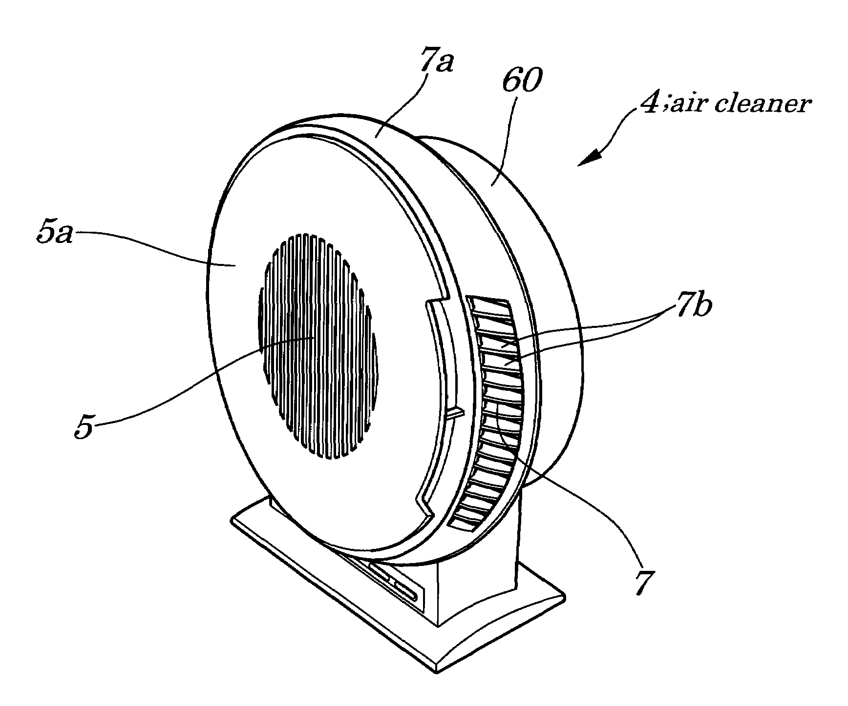
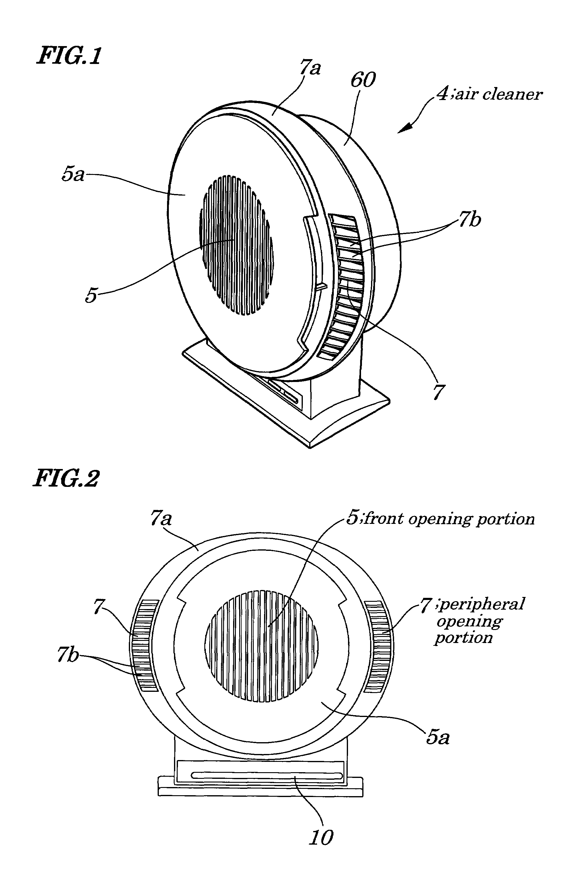
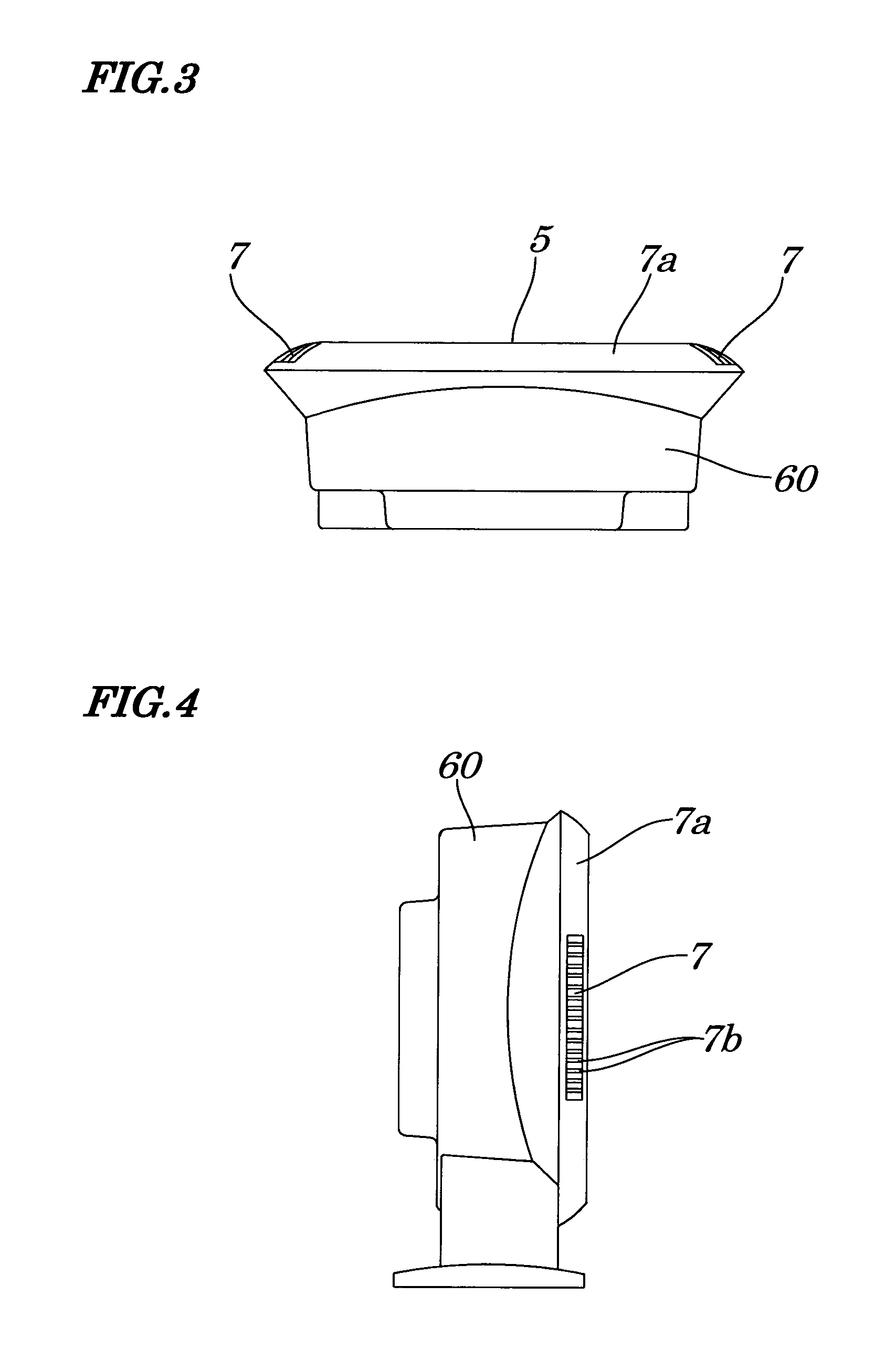
[0041]FIG. 1 is a perspective view schematically illustrating an appearance of configurations of a personal use tabletop-type air cleaner according to a first embodiment of the present invention. FIG. 2 is a front view schematically illustrating the appearance of configurations of the personal use tabletop-type air cleaner of FIG. 1. FIG. 3 is a top view schematically illustrating the appearance of configurations of the personal use tabletop-type air cleaner of FIG. 1. FIG. 4 is a side view schematically illustrating the appearance of configurations of the personal use tabletop-type air cleaner of FIG. 1. FIG. 5 is an exploded perspective view illustrating configurations of the personal use tabletop-type air cleaner of FIG. 1. FIG. 6 is a cross-sectional view schematically illustrating an internal configuration of the personal use tabletop-type air cleaner of FIG. 1. FIG. 7 is a diagram explaining operations of the personal use tabletop-type air cleaner of FIG. 1.

[00...

Example

Second Embodiment

[0049]FIG. 8 is a perspective view schematically illustrating an appearance of configurations of a personal use tabletop-type air cleaner 40 according to a second embodiment of the present invention. Unlike in the case of the first embodiment in which a plurality of blade plates (partitioning plate) 7b are arranged in a horizontal grid form in peripheral opening portions 7 to control a direction of an air flow being emitted, in the second embodiment, as shown in FIG. 8, a plurality of the blade plates (partitioning plates) 71b are arranged in a vertical grid form in the peripheral opening portions 71. By configuring as above, same effects obtained as in the first embodiment can be also obtained. Other parts of the air cleaner 40 are the same as those in the first embodiment, therefore description of them has been omitted.

Example

Third Embodiment

[0050]FIG. 9 is a perspective view schematically illustrating an appearance of configurations of a personal use tabletop-type air cleaner 400 according to a third embodiment of the present invention. Unlike in the case of the second embodiment in which blade plates (partitioning plates) 71b are of a fixed-type plate type, in the third embodiment, as shown in FIG. 9, a plurality of blade plates (partitioning plates) 72b is placed in a manner so as to be rotatable in peripheral opening portions 72 and an air-flow direction control circuit 73 is mounted which is used to electrically control rotation of the blade plates (partitioning plates) 72b.

[0051]Thus, in the configurations of the third embodiment, since a direction of flowing of an emitted air CA can be changed according to a user's preference, further comfort feeling can be obtained.

[0052]Other parts of the air cleaner 400 with same reference numbers are basically the same as those of the first embodiment are the...


PUM

PropertyMeasurementUnit
Distanceaaaaaaaaaa
Distanceaaaaaaaaaa
Efficiencyaaaaaaaaaa

Abstract

A personal tabletop-type air cleaner is provided which is user-friendly and can improve smoke sucking efficiency in a simple configuration. The disclosed personal tabletop-type air cleaner has a front opening portion to suck air containing smoke of a cigarette, a blower to forcedly feed air having been sucked into the front opening portions in a centrifugal manner, a pair of right and left peripheral opening portions each being placed in a fringe portion on the right and the left at a front of the air cleaner and forming an air curtain by emitting air fed forcedly from the blower ahead of the front of the air cleaner, a dust collecting filter being placed between the front opening portion and the blower to remove cigarette odor, and a deodorizing filter being placed between the blower and each peripheral opening portion making up the pair of right and left peripheral opening portions to remove cigarette odor.

Description

BACKGROUND OF THE INVENTION[0001]1. Field of the Invention[0002]The present invention relates to a personal tabletop-type air cleaner to remove smoke of a cigarette, that can be placed on a desk, table, or a like.[0003]The present application claims priority of Japanese Patent Application No. 2002-230668 filed on Aug. 7, 2002, which is hereby incorporated by reference.[0004]2. Description of the Related Art[0005]Conventionally, in an air cleaner of this type, as shown in FIG. 10, a suction port 1 of smoke is placed at a front 1A of the air cleaner and a blow-off port 2 of cleaned air is placed at a rear 2A of the air cleaner. It has configurations of an air flow passage which, figuratively speaking, are reverse to those of a fan. However, the conventional air cleaner has a problem. That is, when such the conventional air cleaner is put at a place being near to a wall or fittings at the rear 2A of the air cleaner, since its blow-off port 2 placed at the rear 2A of the air cleaner is ...

Claims


Application Information

Patent Timeline
IPC IPC(8): B01D46/00B01D50/00A61L9/16B01D46/10B03C3/04F24F8/108F24F8/158F24F8/97
CPCB01D46/0023F24F3/1603B01D2279/00F24F2003/1646F24F2001/0096F24F1/0071F24F8/97B01D46/62F24F8/108F24F8/158B01D46/00
Inventor ENDO, KIYOMU
Owner O DEN CORP TOKIO TOKYO
Why Eureka
Try Eureka