Wire gripper for a drive unit of a wire feeder

a technology of wire feeder and drive unit, which is applied in the direction of manufacturing tools, wound springs, transportation and packaging, etc., can solve the problems of reducing the efficiency of the welding process, the ineffective control system, and the inability to use in the field, and achieves the effect of long service life, convenient field use, and economic manufactur

Active Publication Date: 2006-04-11
LINCOLN GLOBAL INC
View PDF90 Cites 69 Cited by
  • Summary
  • Abstract
  • Description
  • Claims
  • Application Information

AI Technical Summary

Benefits of technology

[0014]In accordance with the present invention, provided is a wire gripper for use in connection with a drive unit of a welding wire feeder which includes a force generator that can be effectively used in connection with a force applicator for feeding a wide range of welding wire without modification to the physical structure of wire gripper. In this respect, a wire gripper in accordance with the present invention includes a force generator having a cylinder spring with at least two spring moduli. The two spring moduli of the cylinder spring are utilized in different portions of the stroke of the cylinder to provide at least two ranges of application force and to provide the desired degree of adjustability for the different ranges of forces.
[0015]A wire gripper according to one aspect of the present invention can utilize two separate cylinder springs such that in a first range of the cylinder's stroke, the cylinder engages only one spring to produce a first range of application force and then in a second range of the stroke, both springs are engaged to produce a second range of application forces. The result is that the spring cylinder according to the present invention can be compact and can work in connection with more than one type of welding wire without physical changes.

Problems solved by technology

As can be appreciated, interruptions in the flow of the welding wire can stop the welding process thereby reducing its efficiency.
But these control systems are effective only if the pinch rollers maintain a constant grip on the wire.
In fact, the application force necessary to accurately move a steel wire would likely damage a copper wire.
Furthermore, a coarse thread will increase the amount of hand force necessary to compress the spring.
One of the problems with prior art force generating devices is that ease of use must be compromised to provide increased adjustability to the application force.
Another problem with prior art force generating devices is that major modifications are necessary in order to obtain the application force necessary to work in connection with a wide range of wire types and wire sizes.
The range of forces needed to work in connection with both soft and hard wires is great enough to necessitate an excessively large spring cylinder and a significant amount of adjustment to change the application force from a desired force for a soft wire to a desired force for a hard wire.
Yet another problem with prior art welding wire feeders is that the necessary adjustability for a soft wire is much different than the necessary adjustability for a harder wire.
But, fine adjustment abilities can be a disadvantage with harder wires.
The fine adjustment can increase the time and effort necessary to make the adjustment.
In view of the fact that the threads utilized in the generator to compress the cylinder spring cannot be easily changed, a cylinder designed for fine adjustment of a soft wire may not even work with a hard wire.
Conversely, a cylinder designed to be used in connection with a hard wire may not have the sensitivity necessary to make the fine adjustments for use in connection with a soft wire.
These types of problems necessitate physical changes to the design of the wire feeder to change from a soft wire to a hard wire.

Method used


Image

  • Wire gripper for a drive unit of a wire feeder
  • Wire gripper for a drive unit of a wire feeder
  • Wire gripper for a drive unit of a wire feeder

Examples


Embodiment Construction

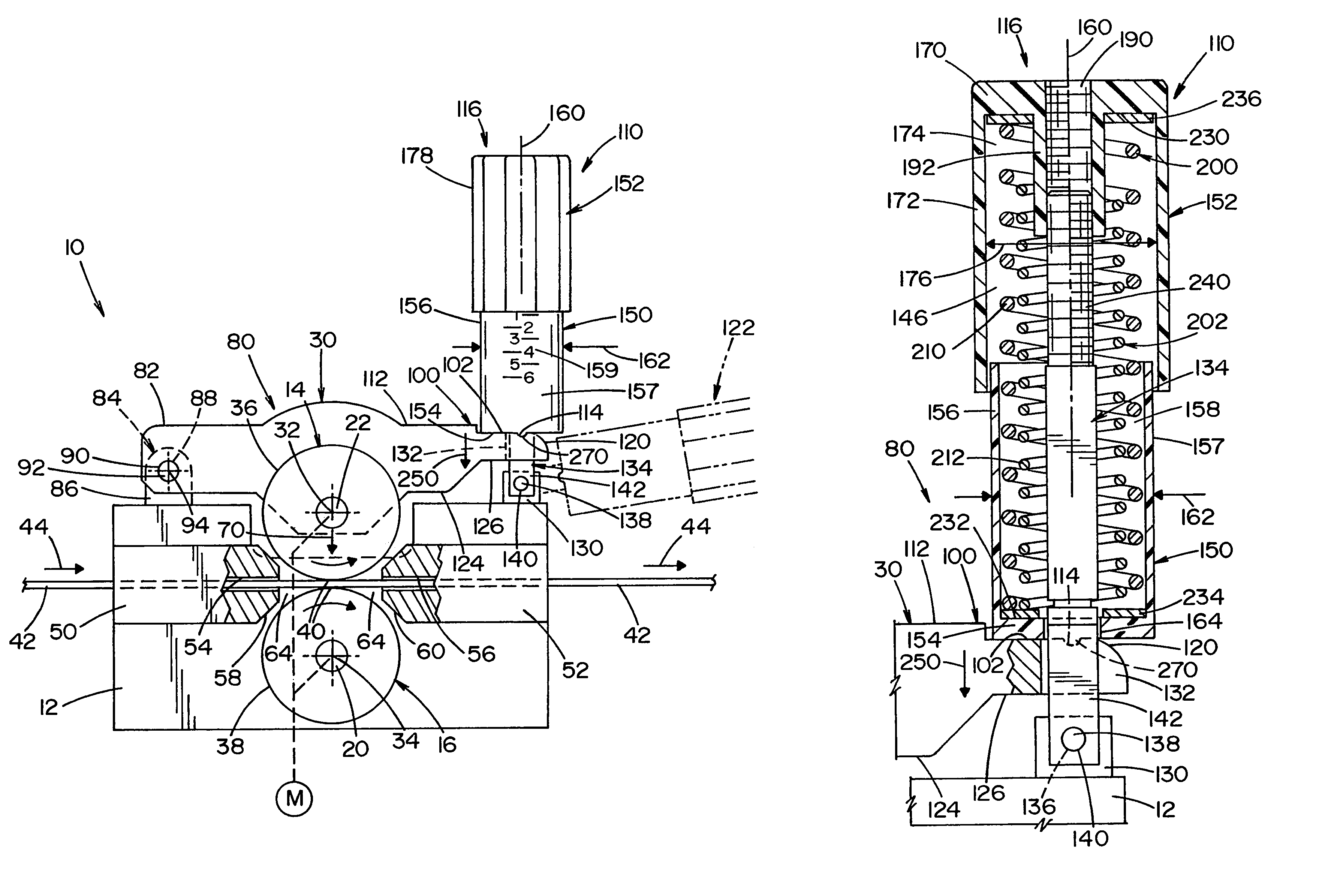
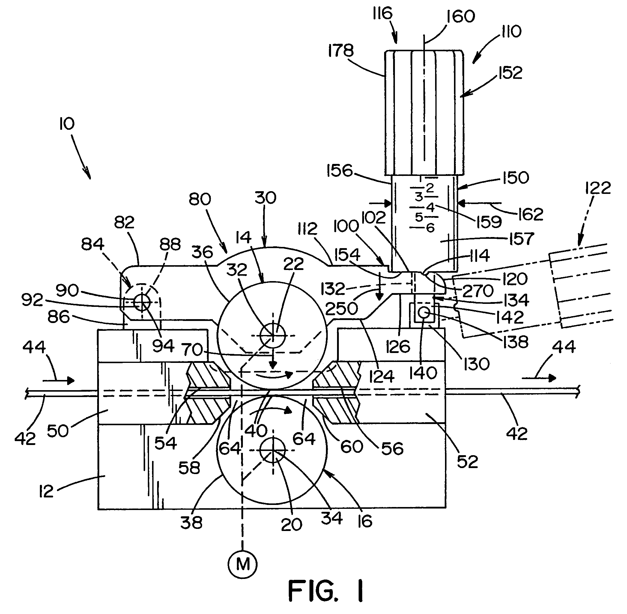
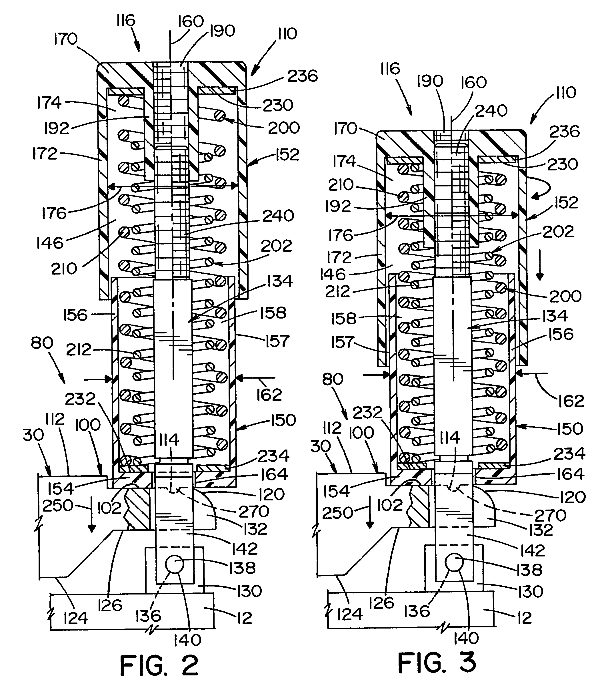
[0037]Referring now in greater detail to the drawings wherein the showings are for the purpose of illustrating preferred embodiments of the invention only, and not for the purpose of limiting the invention, FIGS. 1–4 show a drive unit 10 for a welding wire feeder (not shown). Drive unit 10 includes a support member 12 which is secured to the wire feeder and has a set of pinch rollers 14 and 16. Pinch rollers 14 and 16 are the drive rollers for the drive unit and are connected to an electric drive motor M which is known in the art and schematically shown. As is shown in Seufer, a gear box is used to connected the drive motor to the pinch rollers. It should be appreciated that other drive mechanisms could be used without detracting from the invention of this application. Furthermore, more than one set of drive rollers could also be used in accordance with the present invention.

[0038]Pinch roller 16 is a fixed roller which rotates about a fixed roller axle 20 thereby rotating about a f...


PUM

PropertyMeasurementUnit
spring modulusaaaaaaaaaa
heightaaaaaaaaaa
heightsaaaaaaaaaa

Abstract

A gripping device for a set of pinch rollers used in a wire feeder that supplies a welding operation with a consumable welding wire. The welding wire passes between the pinch rollers whereby the pinch rollers engage the wire with a gripping force and incrementally rotate to control the outflow of the wire to the welding operation. The gripping device has a first member which is displaceable relative to a second member and a spring mechanism extending between the first and second members which has at least a first and a second spring modulus. The spring mechanism produces the gripping force as the first and the second members are displaced toward one another. The gripper urges one roller of the set of pinch rollers toward the other roller of the set to engage the wire and to apply the gripping force. By including a spring with a first and second spring modulus, the gripper can apply a first range of gripping forces with the force produced by the first spring modulus and a second range of gripping forces with the force produced by the second spring modulus.

Description

[0001]This invention relates to the art of dispensing wire and, more particularly, to a wire gripper used in a drive unit of a wire feeder for controlling the force which is applied by the pinch rollers against the wire driven by the wire feeder.INCORPORATION BY REFERENCE[0002]The present invention relates to wire feeders which feed wire to a welding operation wherein the welding wire must be fed in a controlled manner without tangling or interruption. Wire feeders are known in the art and are generally shown and described in Seufer U.S. Pat. No. 5,816,466 which is hereby incorporated by reference herein as background information illustrating the general structure of a wire feeder including two sets of pinch rollers. Sakai 5,053,598 is incorporated herein as background information and illustrates the application of force on the welding wire by the pinch rollers to grip the wire. Hubenko 4,235,362; Gleason 3,694,620; and Okada 3,730,136 are also incorporated by reference herein as ba...

Claims


Application Information

Patent Timeline
Patent Type & Authority Patents(United States)
IPC IPC(8): B23K9/12B65H20/00F16F3/00B23K9/133
CPCB23K9/1336B23K9/124
Inventor BELFIORE, BRIAN J.ENYEDY, EDWARD A.NELSON, BRYAN
Owner LINCOLN GLOBAL INC
Why Eureka
Try Eureka