Relay with a core having an enlarged cross-section

Active Publication Date: 2006-04-11
TYCO ELECTRONICS AUSTRIA
View PDF13 Cites 3 Cited by
  • Summary
  • Abstract
  • Description
  • Claims
  • Application Information

AI Technical Summary

Benefits of technology

[0007]This solution is simple in terms of construction and leads to smaller overall constructions of the relay with a constantly high switching force.
[0008]According to an exemplary embodiment of the invention, the central region of the core, which is surrounded by the coil bobbin, has a reduced cross-section providing space for additional coil windings, so the coil can generate a higher magnetic force. In the transiti

Problems solved by technology

This solution is simple in terms of construction and leads to smaller ov

Method used


Image

  • Relay with a core having an enlarged cross-section
  • Relay with a core having an enlarged cross-section
  • Relay with a core having an enlarged cross-section

Examples


Embodiment Construction

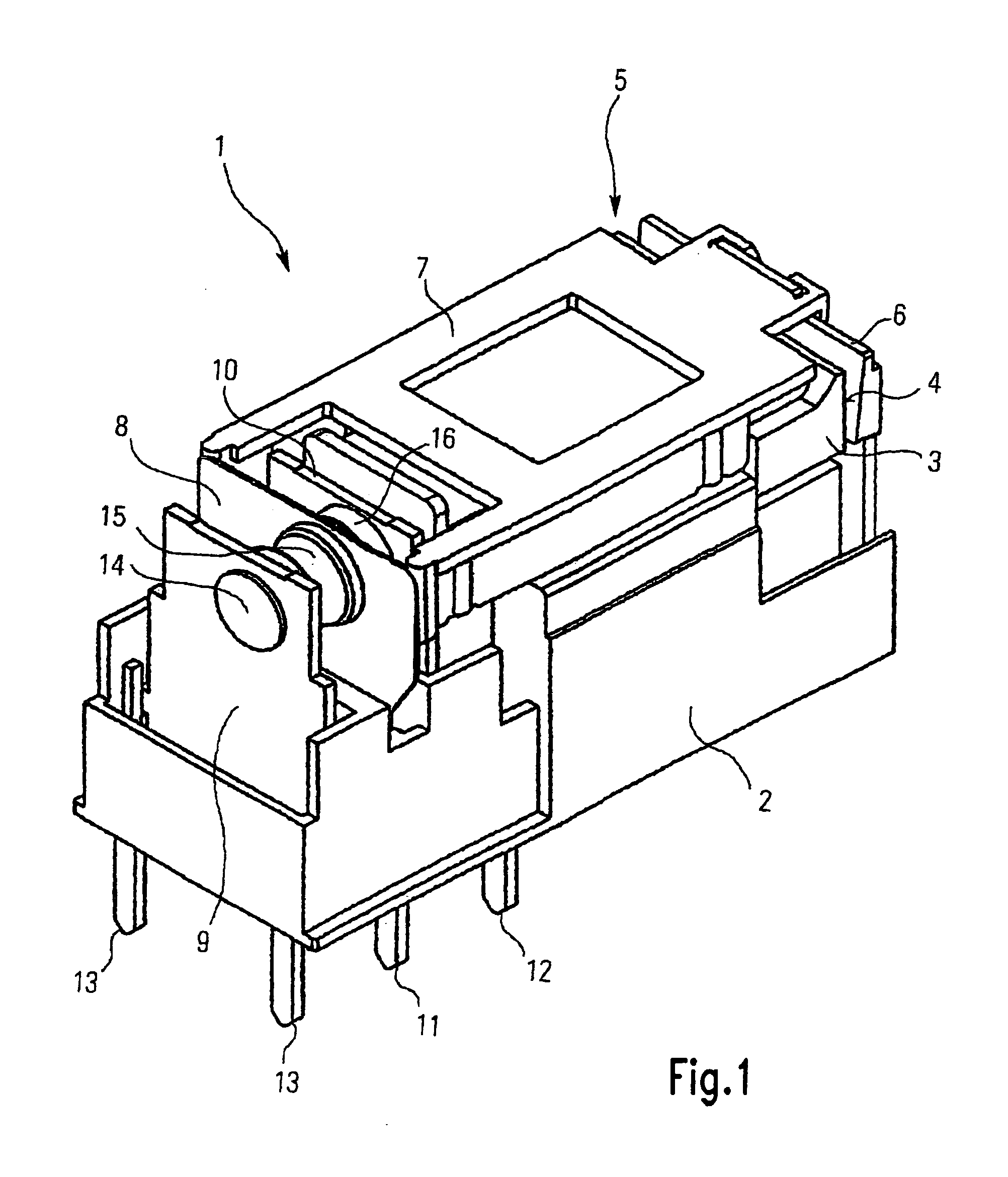
[0020]The general construction of a relay will firstly be described with reference to FIG. 1.

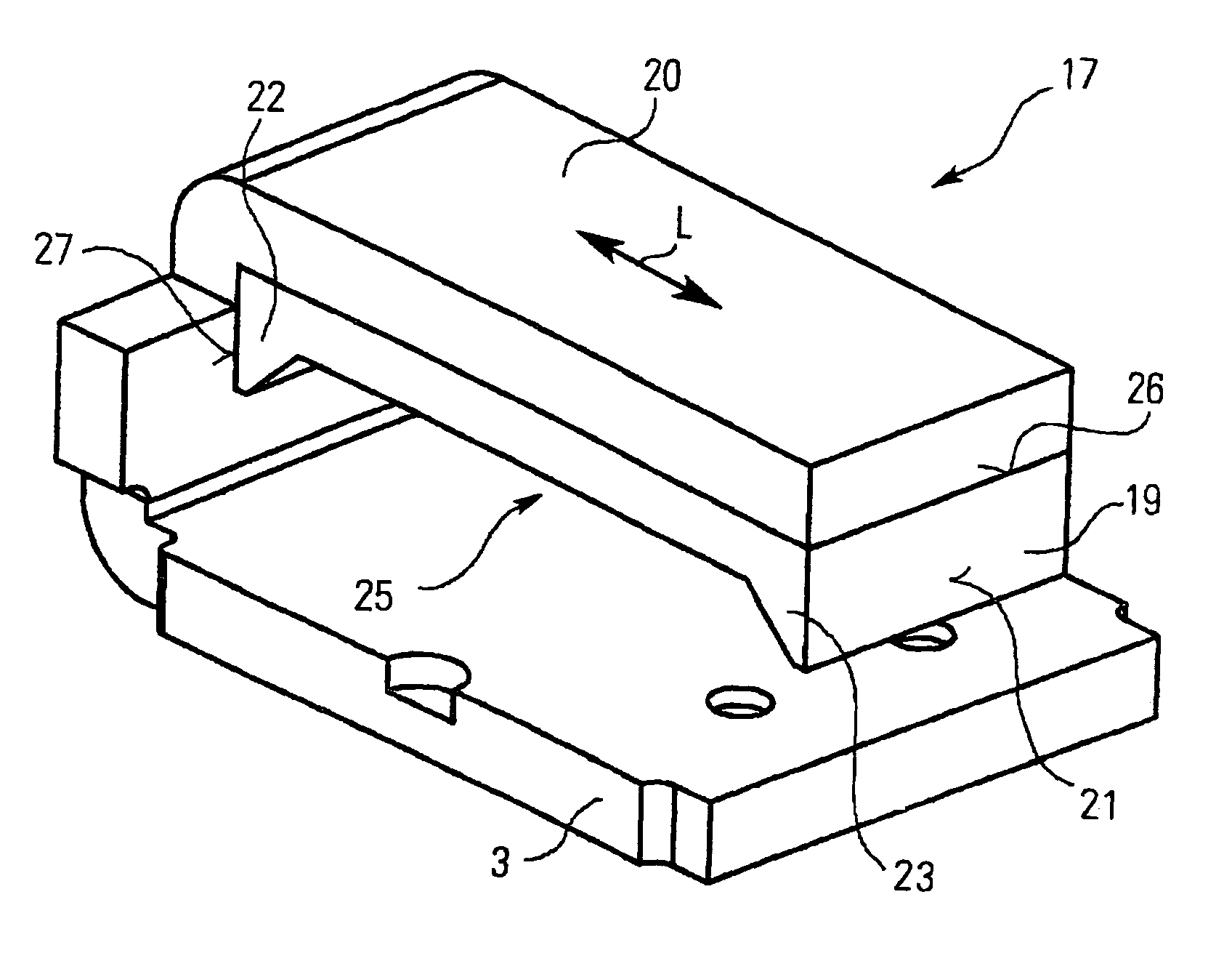
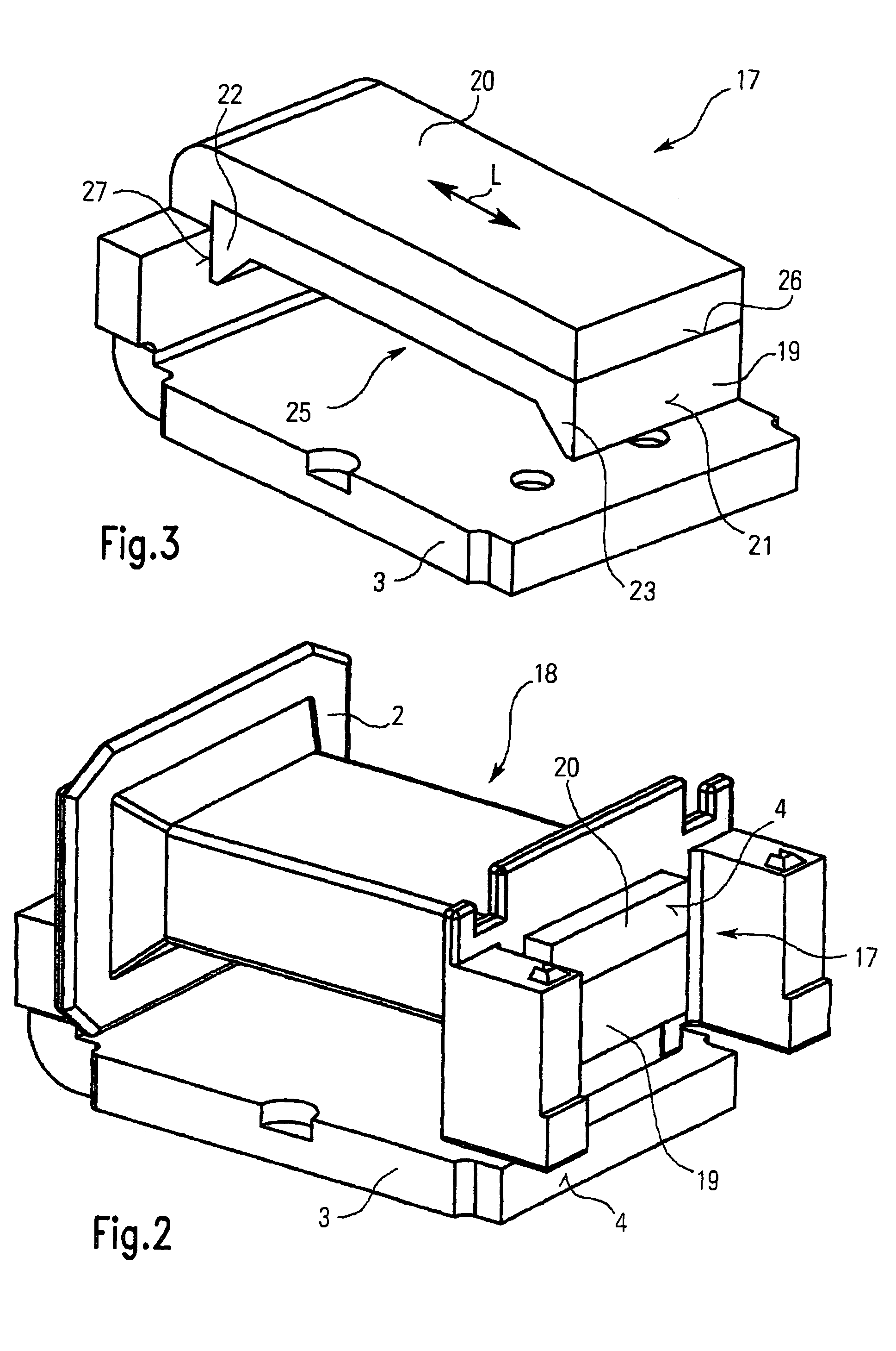
[0021]A relay 1 comprises a coil (not shown in FIG. 1) wound on a coil bobbin 2, a yoke 3, and a core (not shown in FIG. 1) penetrating the coil bobbin 2. The yoke 3 ends in a pole face 4 adjoining a working air gap 5. In other designs the pole face 4 can also be formed on the core.

[0022]The working air gap 5 is arranged between the pole face 4 and a movable armature 6. The armature 6 is connected to a spring contact 8 so as to transmit movement, via a connecting element 7 guided along the coil bobbin 2, so that a movement of the armature 6 inevitably leads to a movement of the spring contact 8.

[0023]The spring contact 8 is in turn arranged between two fixed contacts 9, 10 arranged at a distance from one another in the movement direction of the spring contact, wherein the spring contact can preferably only touch one of the two fixed contacts 9, 10 respectively. The spring contact 8 is conven...


PUM


Abstract

The invention relates to a relay comprising a coil bobbin, a core penetrating the coil bobbin and a yoke. To achieve a high switching force with a low overall height, the cross-sectional area of the core is greater in the region toward the transition to the yoke than in the central region of the coil bobbin. Increased magnetic flux can be conveyed from the core owing to the cross-sectional enlargement and at the same time more coil windings can be arranged in the central region owing to the reduced cross-section there. Both measures act together and allow high switching forces with low overall height.

Description

FIELD OF THE INVENTION[0001]The invention relates to a relay with a coil bobbin, a core penetrating the coil bobbin and a yoke.BACKGROUND[0002]Relays with a coil bobbin, a core penetrating the coil bobbin and a yoke are known, for example, from EP-A-202 651, EP-B-363 176, EP-B-691 667 and DE-C-42 32 228.[0003]In all of these relays the coil bobbin, the core and the yoke form a magnetic system that induces a switching process when the coil is excited or energized. During the switching process, the excited coil, generates a magnetic switching force that moves an armature. The movement of the armature is transmitted to a spring contact which then closes (makes) or opens (breaks) electrical contact with one or more fixed contacts.[0004]One disadvantage of the relays from these known references is that it is difficult to provide adequate switching force with a compact construction.[0005]The object of the invention is therefore to improve a switching relay such that large switching forces...

Claims


Application Information

Patent Timeline
IPC IPC(8): H01H51/22H01F7/06H01H50/16H01H50/36H01H51/06
CPCH01H50/36H01H50/163
Inventor MIKL, RUDOLFMADER, LEOPOLDADRIAN, BERNDHELMREICH, JOHANNES
Owner TYCO ELECTRONICS AUSTRIA
Why Eureka
Try Eureka