Gas injector for injecting gas fuel

A gas injector and gaseous fuel technology, applied in fuel injection devices, special fuel injection devices, fuel injection devices with special measures affecting magnetic flux, etc., can solve problems such as fracture sealing, gas leakage, gas cracks, etc., to achieve High mechanical stability, good welding characteristics, effect of small saturation induction

Pending Publication Date: 2022-06-21
ROBERT BOSCH GMBH
View PDF0 Cites 0 Cited by
  • Summary
  • Abstract
  • Description
  • Claims
  • Application Information

AI Technical Summary

Problems solved by technology

For this reason, magnetic components made of high-performance magnetic materials cannot be used to guide gaseous fuel
Otherwise, there is a ri...

Method used


Image

  • Gas injector for injecting gas fuel
  • Gas injector for injecting gas fuel
  • Gas injector for injecting gas fuel

Examples


Embodiment Construction

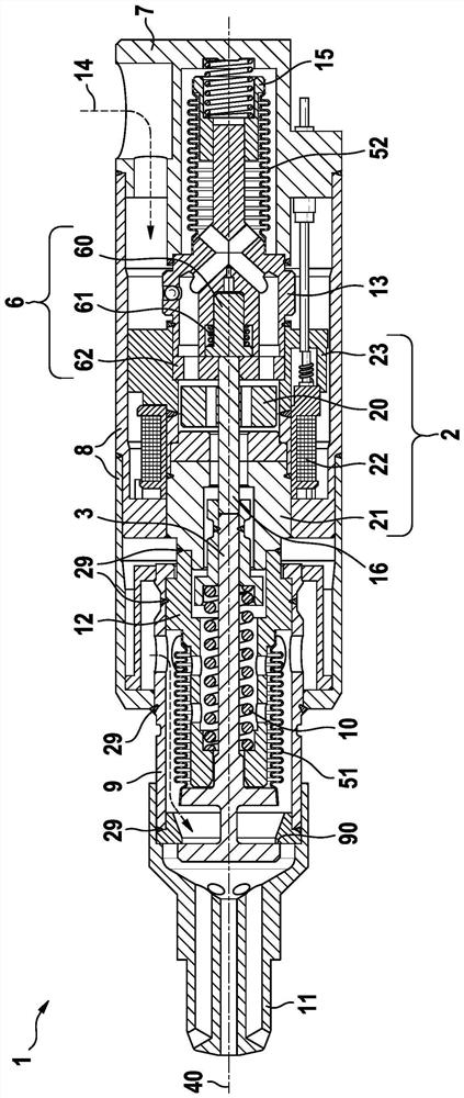
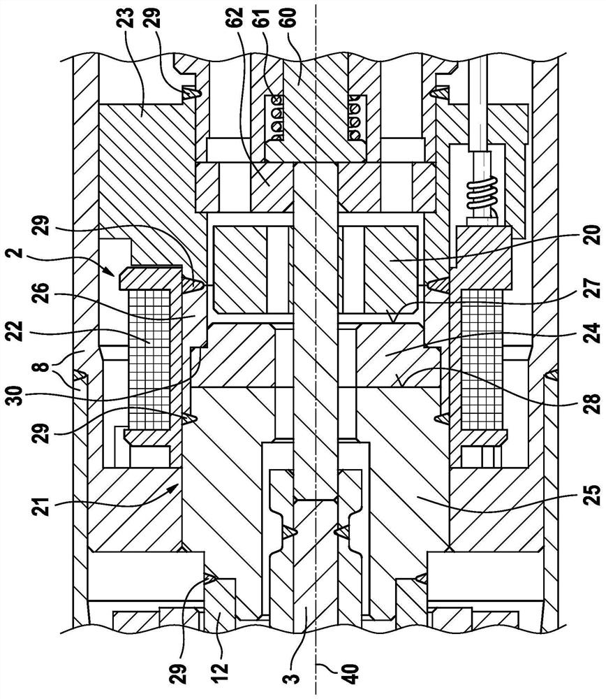
[0021] Refer below Figures 1 to 4 The gas injector 1 according to a preferred embodiment of the present invention is described in detail. like figure 1 and figure 2 As shown in the detailed view in , a gas injector 1 for blowing in gaseous fuel comprises a magnetic actuator 2 which moves a closing element 3 . The closing element 3 extends along the longitudinal axis 40 of the gas injector 1 . In the embodiment shown, the closing element 3 opens outwards. exist figure 1 A closed state is shown for this.

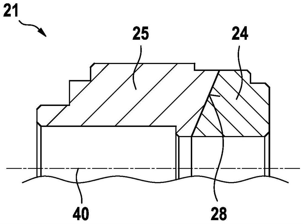
[0022] The magnetic actuator 2 includes an armature 20 which rests on the closing element 3 by means of an armature pin 24 . Furthermore, the magnetic actuator 2 includes an inner pole 21 , a coil 22 and a magnetic housing 23 which ensures the magnetic return of the magnetic actuator 2 .

[0023] Furthermore, the gas injector comprises a body 7 having a lateral port through which the gaseous fuel is supplied. The valve housing 8 is fixed to the main body 7 . The mag...


PUM


Abstract

The invention relates to a gas injector (1) for blowing in gaseous fuel, comprising: a magnetic actuator (2) having an armature (20), an inner pole (21) and a coil (22); and a closing element (3) which releases and closes the gas path (14) on the valve seat (90), the armature (20) being connected to the closing element (3); wherein the inner pole comprises a magnetic pole member (24) close to the armature and a magnetic pole member (25) far away from the armature, and wherein the pole member (24) close to the armature has a greater maximum magnetic current density than the pole member (25) far away from the armature.

Description

technical field [0001] The invention relates to a gas injector for blowing in gaseous fuel, especially hydrogen or natural gas or the like. The gas injector is designed in particular for intake manifold injection or direct injection into the combustion chamber of an internal combustion engine. Background technique [0002] Gas injectors are known from the prior art in various designs. Magnetic actuators for gas injectors must be able to generate higher switching forces and switch correspondingly faster than injectors for liquid fuels. Suitable for this are high-performance magnetic materials with correspondingly high saturation induction and high specific resistance. However, this high performance magnetic material has low stability and poor welding properties. For this, increased porosity occurs compared to standard magnetic materials. For this reason, magnetic components composed of high-performance magnetic materials cannot be used to guide gaseous fuels. Otherwise, ...

Claims


Application Information

Patent Timeline
IPC IPC(8): F02M21/02H01F7/16F02M61/16F02M51/06
CPCF02M21/0254F02M21/0206F02M21/0215H01F7/1607F02M61/16F02M51/0603F02M51/0671F02M2200/08F02M2200/8084H01F7/081
Inventor M·米勒
Owner ROBERT BOSCH GMBH
Why Eureka
Try Eureka