Method and apparatus for extending communications over USB

a communication and usb technology, applied in multiplex communication, sustainable buildings, instruments, etc., can solve the problems of increasing the cost of hubs and the requirement for ac power, the inability to achieve maximum cost-effectiveness, and the inability to connect two downstream hub ports together

Inactive Publication Date: 2006-04-11
INTEL CORP
View PDF9 Cites 70 Cited by
  • Summary
  • Abstract
  • Description
  • Claims
  • Application Information

AI Technical Summary

Problems solved by technology

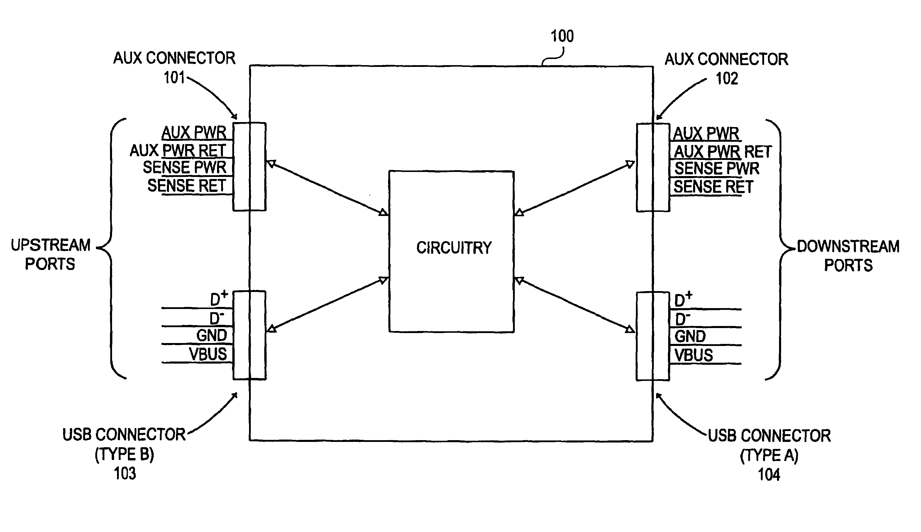
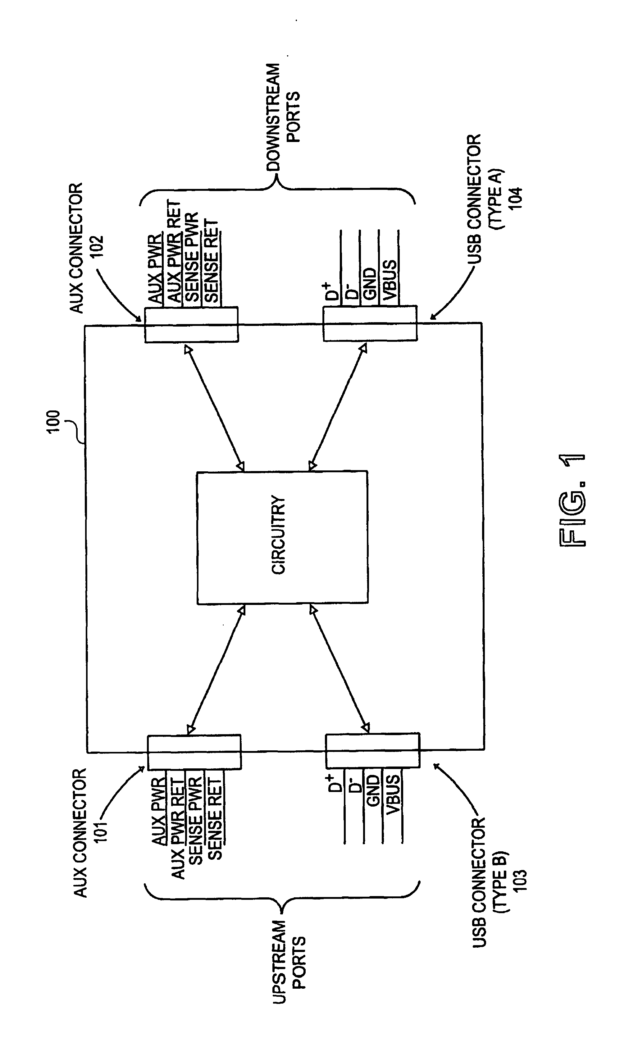
Use of two physically-different types of connectors, along with the cabling defined by the USB specification (described below), means that configuring systems with illegal topologies (such as the connection of two downstream hub ports together) cannot be accomplished.
The USB is actually not a conventional bus, in the sense that generally it does not allow for anything on the bus other than the host controller to be in charge of what is communicated on the bus.
Local extension of the bus may be accomplished through the use of a commercially available hub, although this approach is not likely to be maximally cost-effective.
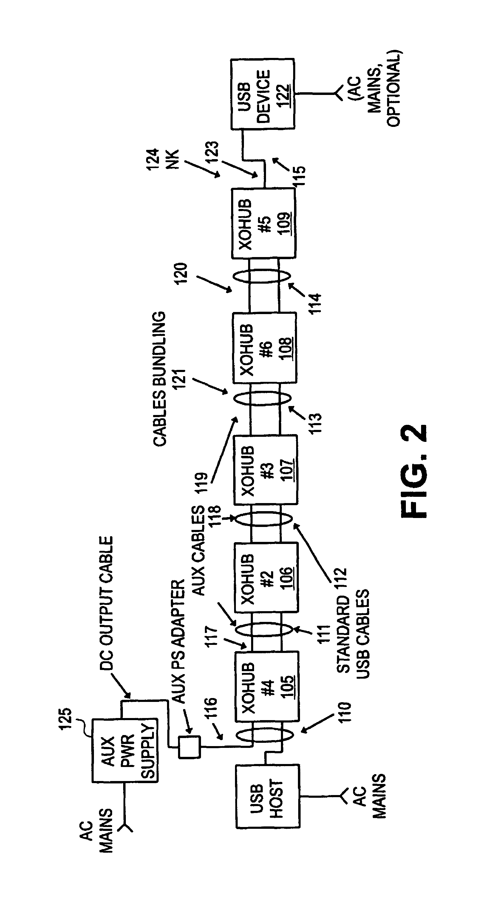
These issues are even more significant in the case of distance extension of the bus, where the cost of the hubs and the requirement for AC power become more important as the extension distance increases.
Additional issues here are the fact that a single, continuous cable cannot be employed to connect the host and device, as well as the 25 to 30 meter total separation distance limitation.
The passive extension approach has the significant disadvantage of compromising signal quality, as well as adversely affecting the USB power voltage drop margins for the unit receiving power from the bus segment.
Unlike the USE system defined in the USB specification, use of passive extension cables can lead to systems which do not function properly, or which may function marginally.
Note for instance that there is nothing to prevent an arbitrary number of passive extenders from being placed in series on any one bus segment.
Since the signaling mechanism employed on the USB segment limits the cable propagation delay and hence the length of the cable, the passive extension approach is clearly not viable for any sort of distance extension of the bus.
Commercially available active repeaters, providing circuitry which buffers the bus segment signals, may allow local extension of the bus to be achieved, but with a similar disadvantage as with passive extension cables of allowing a non- or marginally-functional system to be configured.
The approach however is not the same as the use of actual hubs, since the repeater circuitry is invisible to the OS (in the sense that the OS does not know the repeater is present), and hence the OS cannot regulate the number of repeaters used along the signal path (due also to the fact that the repeater is not controllable by the OS).
A further issue involving the repeater approach is that commercially available repeaters “steal” current from the bus in order to power themselves; the result is that the USB power voltage and / or current available to a device at the far end of a series of repeaters may be marginal.
A yet further issue involving the repeater approach is that commercially available repeaters are implemented using standard USB cabling, which is inadequate to deliver USB power voltage within specification to a device at the far end of a series of repeaters.
Additionally, as with passive extension cables there is nothing to prevent an arbitrary number of repeaters from being placed in series on any one bus segment, allowing systems to be configured which are not able to function, or which can function only marginally.

Method used


Image

  • Method and apparatus for extending communications over USB
  • Method and apparatus for extending communications over USB
  • Method and apparatus for extending communications over USB

Examples


example implementation

3.14 EXAMPLE IMPLEMENTATION

[0477]The schematic diagram for a quad-simplex type long-haul extension unit is shown in FIGS. 23 and 24. The unit is a module which is intended to be designed into a USB product to handle all extension-related signaling. The same module is used to implement both the near-end and far-end extension logic, as controlled by an input signal (HostEnd).

[0478]In this example implementation most of the circuitry is implemented using an FPGA. The top-level schematic diagram for the FPGA circuitry is shown in FIGS. 25 through 33.

[0479]The top and bottom layers of an example PCB layout are shown in FIGS. 34 and 35.

[0480]The schematic diagram for an example test fixture for the module is shown in FIGS. 36 and 37. The test fixture utilizes standard LAN CAT 5 shielded twisted-pair cable for connection between the near- and far-end units. Power is not communicated over the cable.


PUM


Abstract

Method and apparatus are described for improving information transfer over USB. In one approach, hub-based extension is realized wherein power is distributed using auxiliary wiring distinct from signal and power wiring present in conventional USB cabling. Additional signals allow optimization of power distribution for powering attached devices, and for detecting and handling illegal connection configurations.In another approach, improvements are realized through use of alternative signaling techniques which eschew reflective and high-speed common-mode signaling. Described are various configuration, media and signal-protocol combinations, including implementations containing embedded hubs. Methods ensuring reliable system behavior are also described, including determination of extension path delay and use of topology-enforcement hubs.In other approaches, further improvements are realized by allowing information exchanges to take longer than the nominal timeout period, or by allowing host requests to be delayed for transmission until the extended bus is available for use.

Description

RELATED APPLICATION DATA[0001]This application claims priority from U.S. provisional patent applications, Ser. Nos. 60 / 131,941, filed Apr. 30,1999, and 60 / 134,769, filed May 18, 1999.OVERVIEW[0002]This invention relates to the interconnection of computers and peripherals, and more particularly to interconnections compliant with the Universal Serial Bus (USB) standard. USB is a relatively recently-developed standard defining the connection of personal computers (PCs) and peripheral devices, and is formally presented in the Universal Serial Bus Specification, Revision 1.1, dated Sep. 23, 1998, incorporated herein by reference, as well the Universal Serial Bus Specification, Revision 2.0, dated Apr. 27, 2000, incorporated herein by reference. References in the text below to Sections, Figures and Tables refer to items in the USB specification, while references to FIGs are to figures specific to this application.[0003]This section presents an overview of relevant features of the USB.1.1 ...

Claims


Application Information

Patent Timeline
Patent Type & Authority Patents(United States)
IPC IPC(8): G06F13/38G06F13/00G06F13/40
CPCG06F13/385G06F13/4045Y10S370/906Y02B60/1235Y02B60/1228Y02D10/00
Inventor JACKSON, DANIEL KELVIN
Owner INTEL CORP
Why Eureka
Try Eureka