
Device for continuous drying of material

a technology of continuous drying and material, applied in drying machines, lighting and heating apparatus, furniture, etc., can solve the problems of insufficient drying, clogging of matrices, and excessive drying of materials, and achieve the effect of reducing environmental pollution

Active Publication Date: 2006-04-18
ANDRITZ INC
View PDF4 Cites 13 Cited by
  • Summary
  • Abstract
  • Description
  • Claims
  • Application Information

AI Technical Summary

Benefits of technology

This solution ensures even distribution and continuous drying of materials, reduces clogging and shutdowns, and provides a reliable, low-cost, and environmentally friendly drying process with automatic control of material discharge.

Problems solved by technology

Their disadvantage to date has been uneven distribution of the material on the revolving belt, particularly filter belt, which causes excessive drying of the material in places where the layer was too thin and insufficient drying at other points where the layer was too thick.
Practice has shown that these matrices tend to become clogged due to foreign matter in the product to be dried, which in turn has a very disadvantageous effect on even drying.
In addition, these systems are highly sensitive to changes in the sludge properties.

Method used


Image

  • Device for continuous drying of material
  • Device for continuous drying of material
  • Device for continuous drying of material

Examples


Embodiment Construction

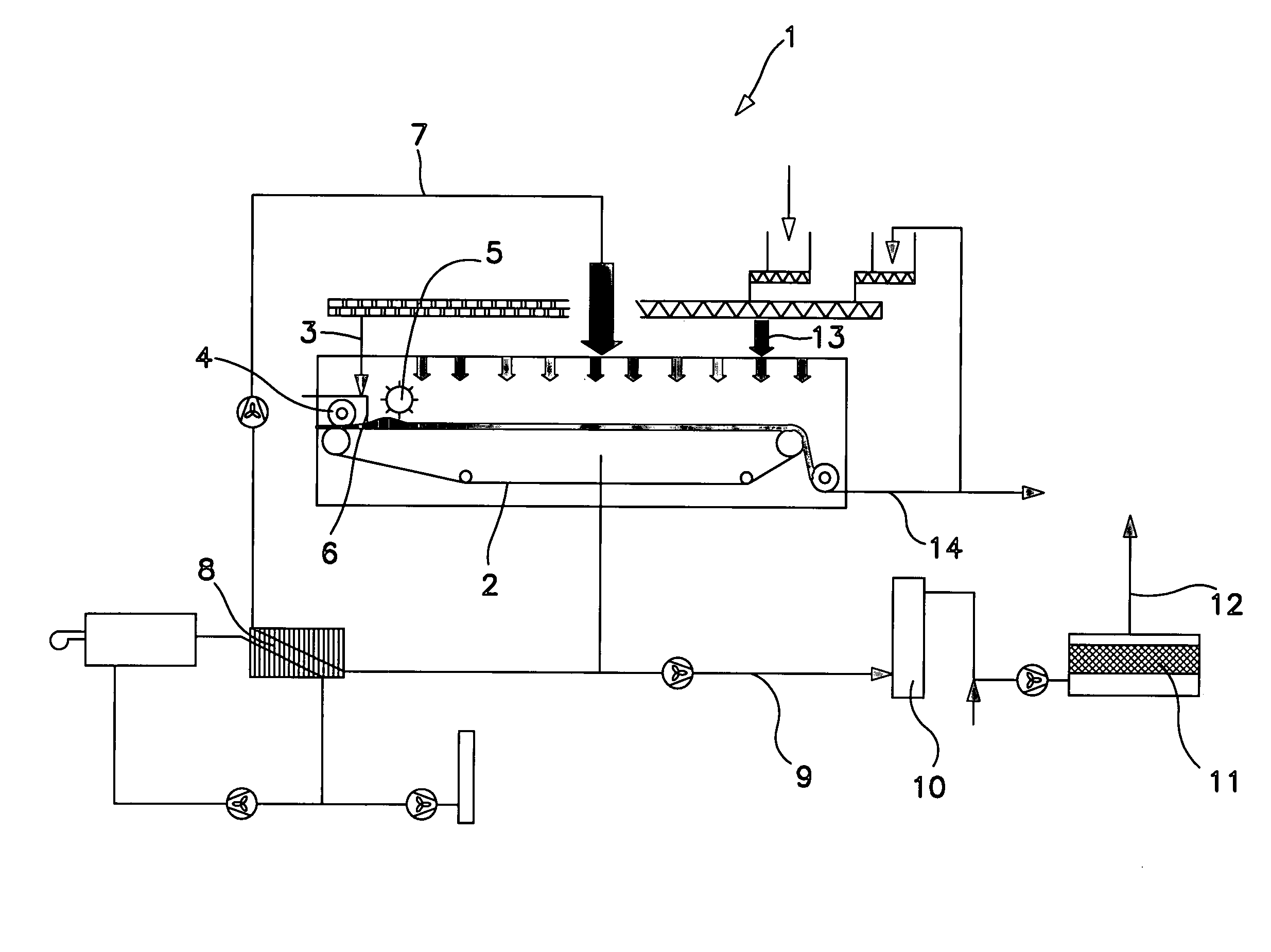
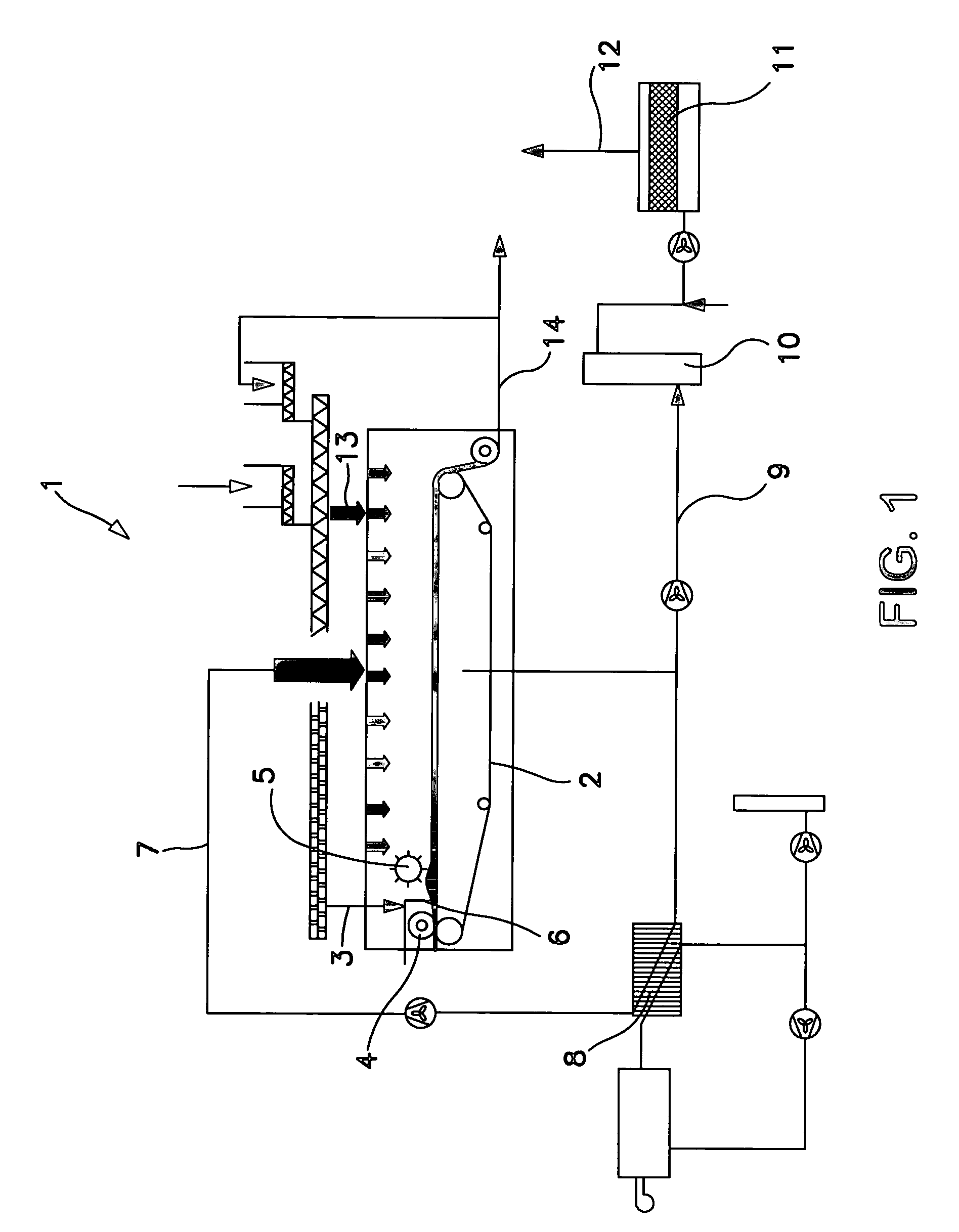
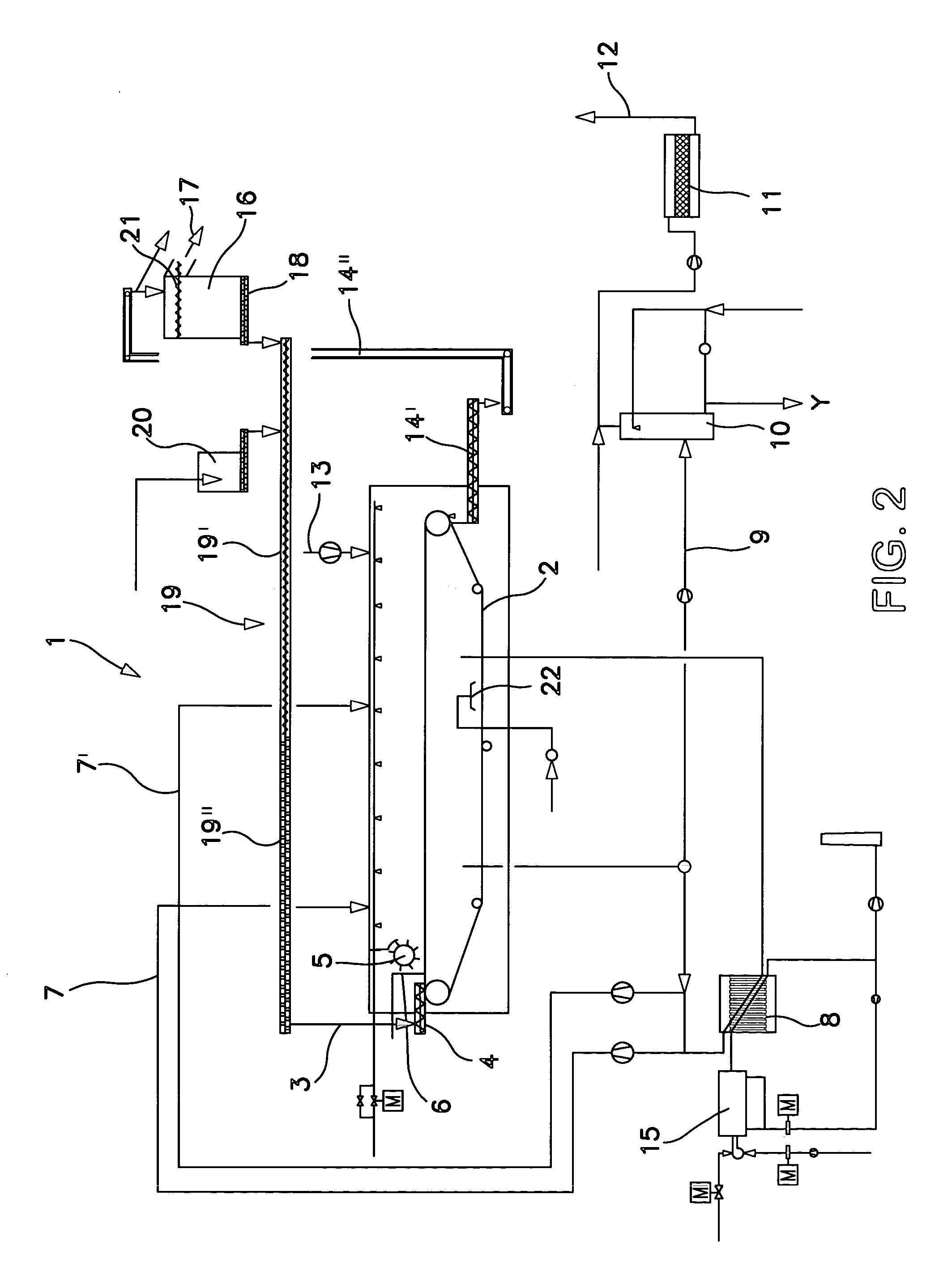
[0023]FIG. 1 is a schematic diagram of a dryer 1 with a belt, particularly a filter belt 2, in which material 3 to be dried is fed through a distribution screw onto the belt, particularly filter belt 2, and then evened out by a calibrating roll 5. The belt, particularly filter belt, used here can be made of plastic or metal fabric. In the vicinity of the distribution screw 4 there is a level sensor 6 that controls the belt speed, where the belt, particularly filter belt, accelerates when the level in the distribution screw rises and the belt speed is reduced when the level in the distribution screw drops, until the level returns to the set value. Since the material is thrown backwards by the calibrating roll 5, even distribution is achieved after the calibrating roll on the one hand, and on the other hand, at higher feed levels the material is directed into the vicinity of the sensor, which means that the belt speed control is triggered promptly.

[0024]Drying is effected by hot air f...


PUM

PropertyMeasurementUnit
heightaaaaaaaaaa
speedaaaaaaaaaa
conveying speedaaaaaaaaaa

Abstract

The invention relates to a device for device for continuous drying of material, particularly sewage sludge, which has a belt 2, particularly a filter belt, on which the material is conveyed. It is characterised by a distribution screw 4 being mounted above the belt 2, particularly filter belt, at the inlet in order to feed the material onto the belt 2, particularly filter belt. In addition, the invention relates to a process for drying material, particularly sewage sludge, where the material is conveyed on a belt 2, particularly a filter belt, through a dryer 1, which process is characterised by the material being fed in through a distribution screw 4, where the level can be changed by altering the belt speed.

Description

BACKGROUND OF THE INVENTION[0001]The invention relates to a device for continuous drying of material, particularly sewage sludge, which has a belt, particularly a filter belt, on which the material is conveyed. In addition, the invention relates to a process for drying material, particularly sewage sludge, where the material is conveyed on a belt, particularly a filter belt, through a dryer.[0002]Belt dryers have long been used for different purposes. Their disadvantage to date has been uneven distribution of the material on the revolving belt, particularly filter belt, which causes excessive drying of the material in places where the layer was too thin and insufficient drying at other points where the layer was too thick. When paste-like and / or sticky substances, e.g. sewage sludge, are dried, they have to be shaped into particles as close to the same size as possible before being distributed evenly over the belt, particularly a filter belt. This is achieved in plants for sewage sl...

Claims


Application Information

Patent Timeline
Patent Type & Authority Patents(United States)
IPC IPC(8): F26B25/00F26B5/04C02F11/16F26B1/00F26B11/02F26B17/04F26B19/00F26B21/04
CPCF26B1/00F26B17/04F26B25/002F26B25/005F26B21/04F26B2200/18
Inventor VONPLON, ARMIN
Owner ANDRITZ INC
Learn More