Low flow bailer system

a bailer system and low flow technology, applied in the direction of fluid removal, component separation, withdrawal sample devices, etc., can solve the problems of inability to control the flow rate of the sample, serious problems, and the inability to guarantee the integrity of the sample, and achieve the effect of negative buoyancy of the apparatus

Inactive Publication Date: 2006-04-18
LOW FLOW BAILER SYST
View PDF6 Cites 6 Cited by
  • Summary
  • Abstract
  • Description
  • Claims
  • Application Information

AI Technical Summary

Benefits of technology

[0012]In satisfaction of these and related objectives, Applicant's present invention provides a bailer of an improved design which allows for the variance of flow into the bailer through use of attachments with varying inflow orifice sizes. As the size of the orifice changes, the weight of the apparatus can also be changed allowing for an only slightly negative buoyancy of the apparatus. The attachment may also be designed to include features for filtering unwanted particulates from the sample.

Problems solved by technology

However, inherent in the presently-known bailer designs, is the inability to control the flow rate of the sample—a serious problem in light of relatively new knowledge concerning factors affecting the quality of samples taken in test wells.
It has been determined that if the extraction rate exceeds the recharge rate, the sample may be compromised through various means, including the increase of the turbidity of the sample, the mixing of stagnant and fresh water in the well, and the disturbance and re-suspension of settled solids.
Resulting guidance documents now state that bailers are ill-suited for low flow.
Thus, use of conventional bailers for test well sampling is very nearly obsolete.
Ironically, although the pump flow rates are easily controlled, the problems associated with using pumps at test well sites are the very reasons that most samplers changed from using pumps to using bailers in the past.
Pumps are expensive, harder to clean and operate, and require an external power source.
Pumps also have go through general maintenance procedures to maintain the life of the pumps, increasing the cost.

Method used


Image

  • Low flow bailer system
  • Low flow bailer system

Examples


Embodiment Construction

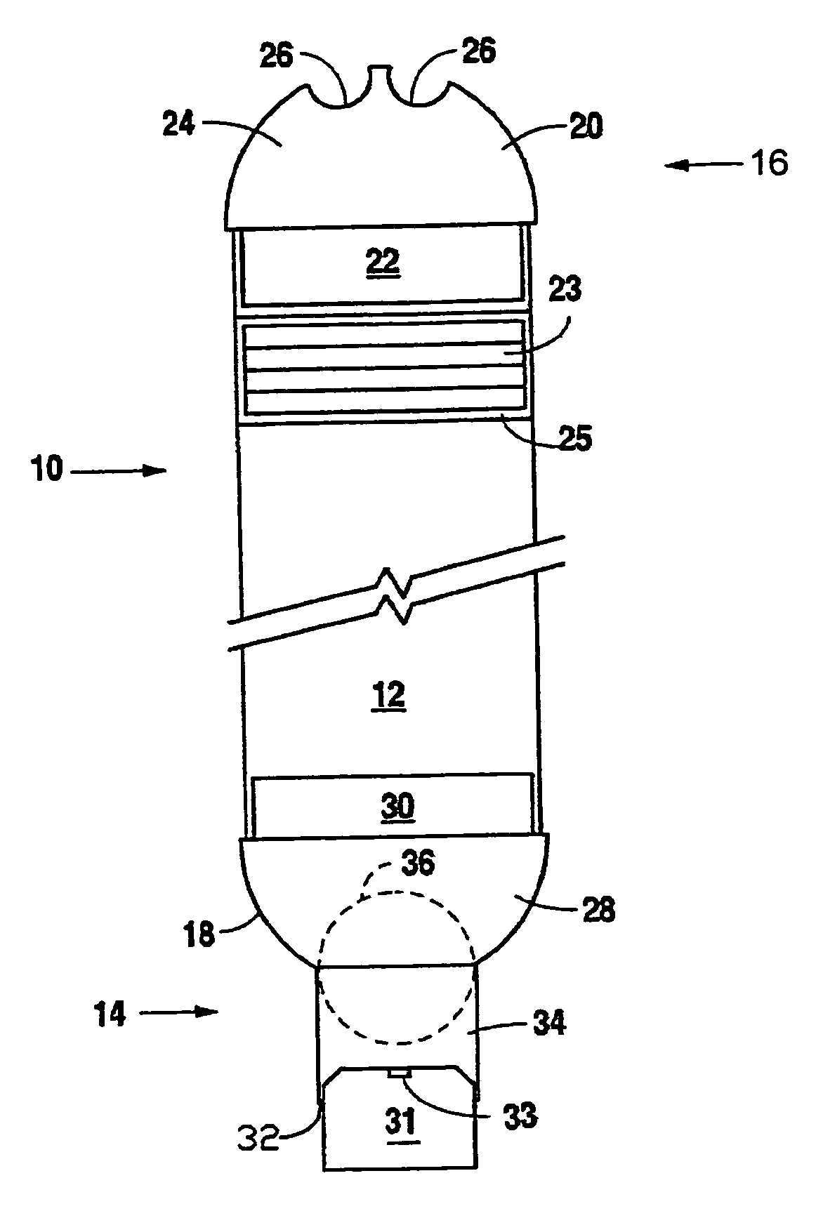
[0015]Referring to FIG. 1, the bailer of Applicant's invention is identified by the reference numeral 10. The preferred embodiment of bailer 10 includes a cylindrical, plastic tube 12.

[0016]The bailer has an insertion or distal end 14 and a proximal end 16. The preferred embodiment of Applicant's bailer 10 includes a distal terminus cap 18 and a proximal terminus cap 20, and a negative buoyancy device 23 and housing 24. Proximal terminus cap 20 includes a generally dome-shaped portion 24 from which extends a nesting lip 22.

[0017]Nesting lip 22 extends from the margin of the dome portion 24 of cap 20 to generally define a cylindrical structure which snugly nests within the lumen of plastic tube 12. To insure that proximal terminus cap 20 does not accidentally disengage from plastic tube 12, the two should be suitably bonded together (such as through use of sonic welding) during assembly of bailer 10 through means appropriate for the material from which bailer 10 is fabricated (polyet...


PUM

PropertyMeasurementUnit
symmetryaaaaaaaaaa
buoyancyaaaaaaaaaa
flow rateaaaaaaaaaa

Abstract

An improved bailer which allows for the variance of flow into the bailer through use of attachments with varying inflow orifice sizes. As the size of the orifice changes, the weight of the apparatus can also be changed allowing for an only slightly negative buoyancy of the apparatus. The attachment may also be designed to include features for filtering unwanted particulates from the sample.

Description

BACKGROUND OF THE INVENTION[0001]1. Field of the Invention[0002]Applicant's invention relates to apparatuses for retrieving liquid samples from reservoirs of liquid.[0003]2. Background Information[0004]Groundwater pollution is an ever-growing concern in today's environments, and the need for groundwater monitoring is increasing, especially around chemical storage facilities, land fills, military bases, airports, and underground storage tanks.[0005]The typical groundwater monitoring program consists of a series of monitoring wells located at different points around the margin of an aquifer, in close and distant proximities from the potential contamination source. Each monitoring well consists of a well casing which lines the well bore, the hole extending from the ground surface to the groundwater.[0006]At least until very recently, most monitoring samples have been taken through the use of devices known as bailers. A bailer is an elongated, slender tube which is sized to pass through...

Claims


Application Information

Patent Timeline
Patent Type & Authority Patents(United States)
IPC IPC(8): G01N1/12E21B27/00G01N33/18
CPCG01N1/12G01N33/18
Inventor VOSS, GENE A.
Owner LOW FLOW BAILER SYST
Why Eureka
Try Eureka