
Light cove

a technology of light coves and coves, applied in the field of light coves, can solve the problems of inability to schedule non-electrical work, need rework, errors, etc., and achieve the effect of simple engaging and disengaging connection and easy disengagemen

Inactive Publication Date: 2006-04-18
USG CEILINGS PLUS LLC
View PDF13 Cites 18 Cited by
  • Summary
  • Abstract
  • Description
  • Claims
  • Application Information

AI Technical Summary

Benefits of technology

[0009]These and other problems are successfully addressed and overcome by the present invention. Either the structural parts or the electrical parts may be first secured to the wall, and a panel section including the shroud is then placed onto the structural parts. Specifically, top and bottom spaced-apart fastening devices are separately secured to the wall. A panel section is pivotally secured preferably to the bottom fastening device by a hinge arrangement, and to the top fastening device by an adjustable support. A simple engaging and disengaging connection between the panel section and the adjustable support enables the panel section to be easily disengaged from the adjustable support so that the panel section can be downwardly pivoted with respect to the bottom fastening device. The shroud is amenable to the inclusion of decorative and acoustic control material and other features.
[0010]Several advantages are derived from this arrangement. The installation is easily made. Scheduling of the electrical and the structural workers need not be coordinated at exactly the same time, thereby avoiding conflict between the electrical and non-electrical work. Because the top and the bottom fastening devices are separate, problems relating to uneven walls are minimized. Placement and replacement of light bulbs is simplified; pivoting of the panel section provides easy access to the light fixture. In general, costs are reduced.

Problems solved by technology

Coordination and other problems occur because the electrical and structural work is not integrated but performed separately, and it is not infrequent that both electrical and non-electrical work cannot be scheduled at the same time.
Therefore, errors can arise and rework is needed.
When a fluorescent or other light bulb burns out, it is generally not easy to replace the bulb because of the integrated structural and electrical installation; therefore, a more skilled worker may be required, possibly resulting in additional scheduling and cost problems.
Furthermore, because the structural parts are so fabricated as a unit, it may become an installation problem or, at least, difficulties may be experienced when the wall, to which the fixture is to be attached, is uneven.
Also, existing assembles often permit stray light to escape from the assembly.
The assembly is not amenable to providing for changes in aesthetic appearance or for incorporation of other features, such as acoustic materials because of its unitary and integrated electrical and structural construction.

Method used


Image

  • Light cove
  • Light cove
  • Light cove

Examples


Embodiment Construction

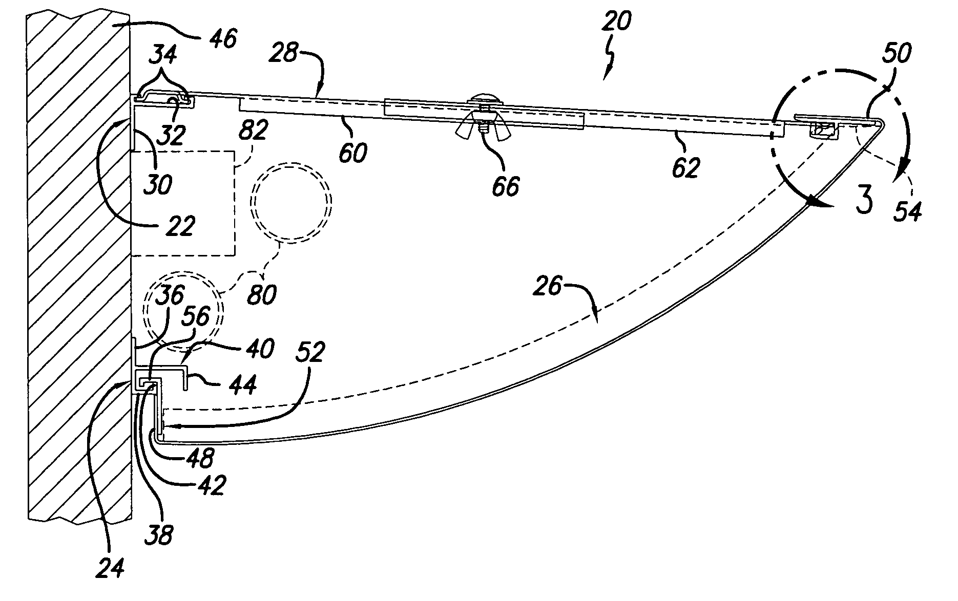
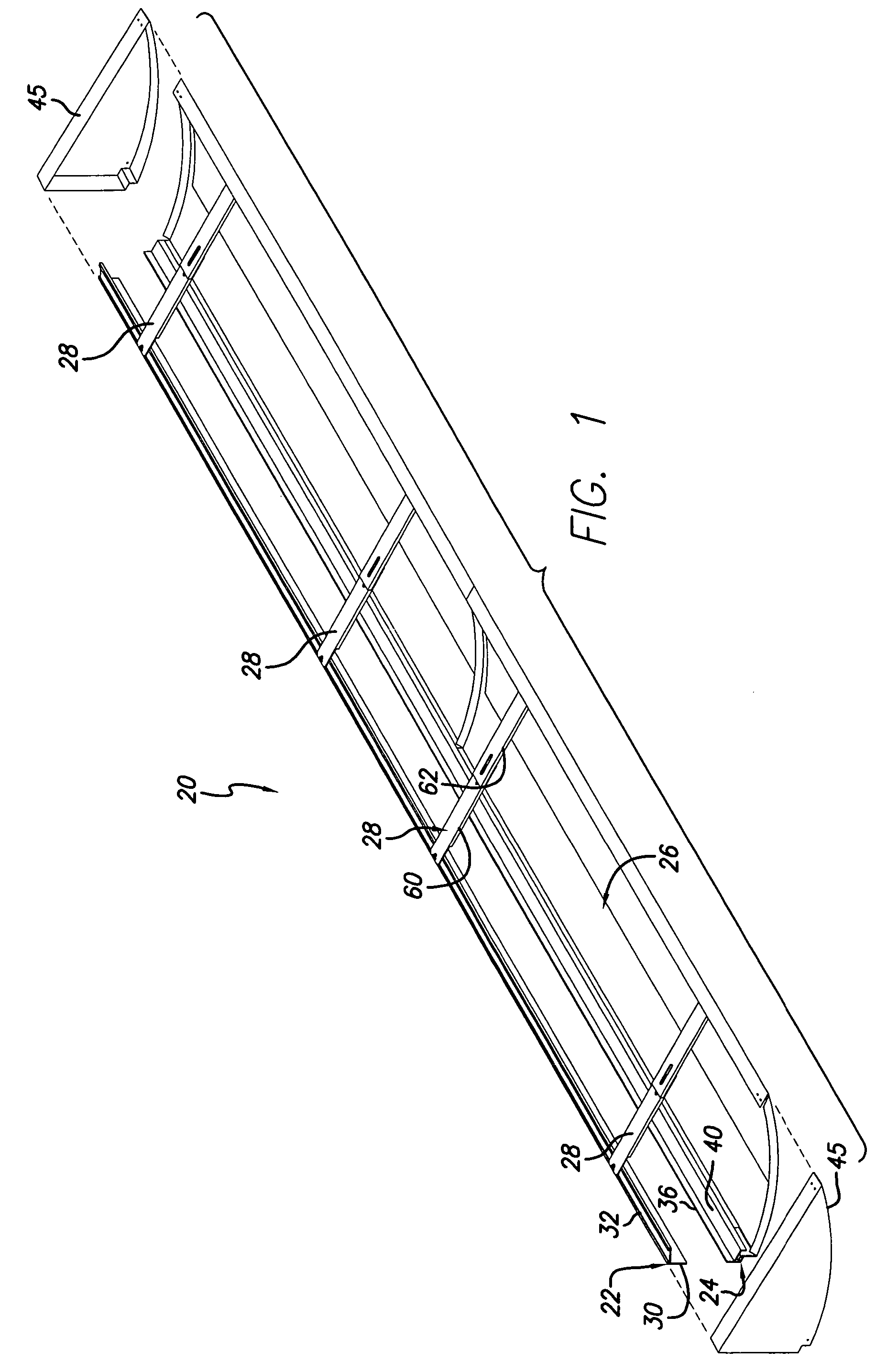
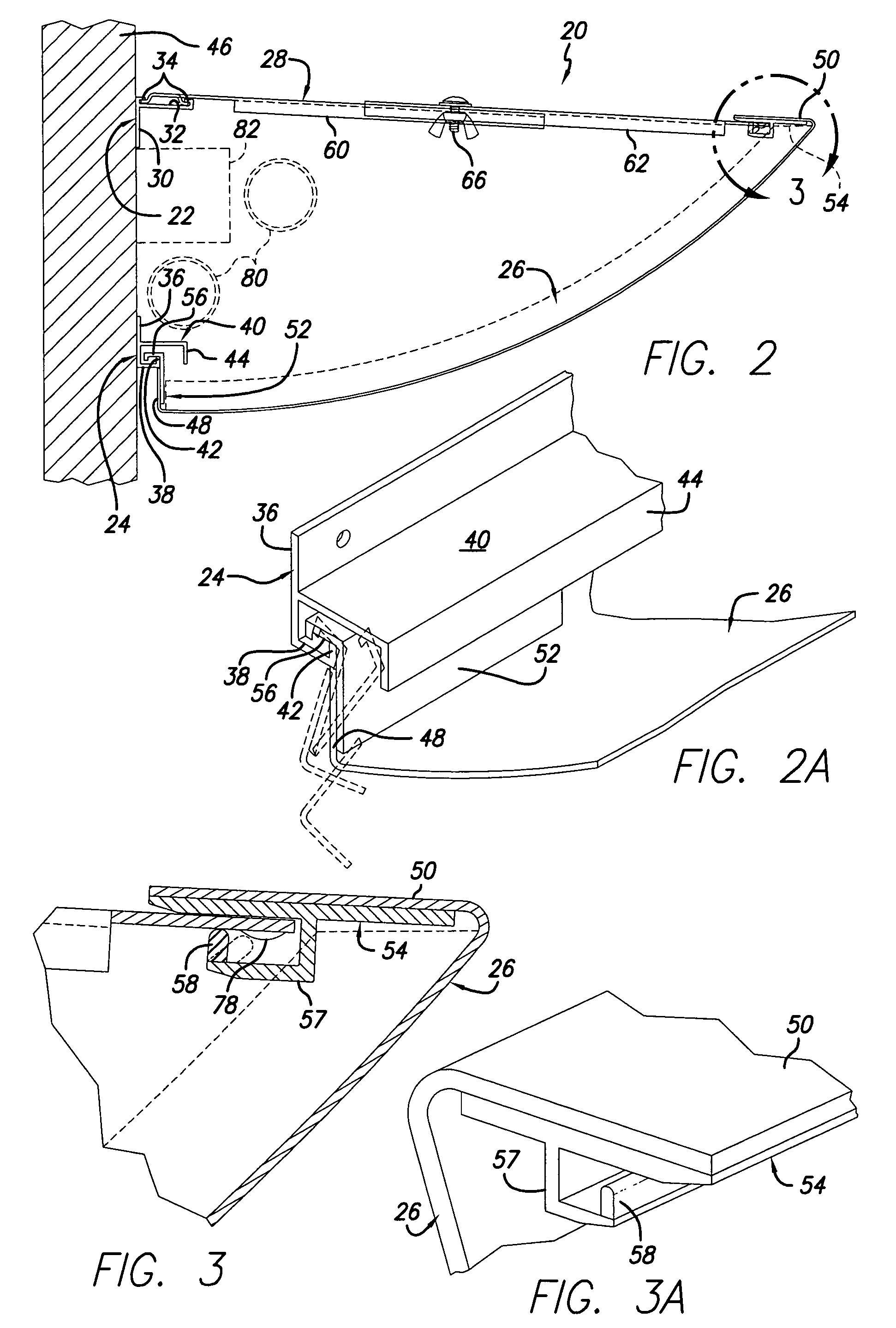
[0020]Accordingly, a light cove 20 includes separate elongated top and bottom fastening devices 22 and 24, a light-transparent panel or shroud section 26, and a plurality of two-piece adjustable supports 28. Top fastening device 22 includes a backing plate 30 and a channel 32 extending perpendicularly therefrom. As best depicted in FIGS. 2 and 2A, channel 32 has a generally U-shaped configuration with a pair of rails 34 extending towards one another. Bottom fastening device 24 includes a backing plate 36, a channel 38 and an overhang 40, both of which extend perpendicularly from backing plate 36. Channel 38 has a generally U-shaped configuration with an upwardly extending rail 42. Overhang 40 has a downwardly extending portion 44 which is disposed to hang over U-shaped channel 38. Both fastening devices 22 and 24 may be formed of extruded aluminum stock. Panel section 26 may comprise a construction including a light-transparent or translucent material which additionally may be modif...


PUM


Abstract

A light cove (20), which is adapted to be secured to a wall (46), includes elongated top and bottom fastening devices (22) and (24), a light-transparent panel section (26), and a plurality of two-piece adjustable supports (28). A light fixture (82) with one or more bulbs (80) is positioned intermediate to the top and bottom fastening devices, and all three elements are separately securable to a wall (46) for accommodating any unevenness of the wall and to provide maximum adjustment among the three parts. The panel section is pivotally couplable to the bottom fastening device and can be articulated upwardly so as to position its end (50) adjacent to the adjustable supports. The supports include a strap (62) having projections (78) which can be snapped past a snap-in lip (58) to form a secure joint between the strap and the panel section. After proper positioning of the panel section with respect to the wall and its surroundings, a plurality of screw and wing nut couplings (66) in the adjustable supports are fully tightened to complete the installation of light cove. When it is necessary to change the bulbs or clean or replace any parts of the panel section or the light fixture, it is only necessary to reverse the above-described installation.

Description

CROSS-REFERENCE TO RELATED APPLICATION[0001]This application claims the benefit of U.S. Provisional Application No. 60 / 420,377, filed 22 Oct. 2002.REFERENCE REGARDING FEDERAL SPONSORSHIP[0002]Not ApplicableREFERENCE TO MICROFICHE APPENDIX[0003]Not ApplicableBACKGROUND OF THE INVENTION[0004]1. Field of the Invention[0005]The present invention relates to a light cove and, in particular, to improvements in securing a light fixture and its shrouding structure to a wall.[0006]2. Description of Related Art and Other Considerations[0007]Known light cove assemblies include an integrated electrical and structural construction which requires separate installation of the electrical and structural components. The electrical work is generally first made into a wall, followed by placement of rails onto the wall. A shroud structure is then secured to the rails over at least a portion of the electrical component. Further electrical work may be needed. Coordination and other problems occur because t...

Claims


Application Information

Patent Timeline
Patent Type & Authority Patents(United States)
IPC IPC(8): F21S8/00F21V15/01F21V15/015F21V19/04
CPCF21S8/033F21V15/01F21Y2103/00F21V19/04F21V15/015
Inventor KIECHLE, ALBERTEISNER, LESTER
Owner USG CEILINGS PLUS LLC
Learn More