Laser alignment device of a circular saw machine

a circular saw machine and laser alignment technology, which is applied in the direction of metal sawing accessories, lighting and heating apparatus, instruments, etc., can solve the problems of low production efficiency, long assembly time, and wrong cutting dimension, and achieve the effect of raising the accuracy of the laser alignment devi

Inactive Publication Date: 2006-04-18
TUNG HSIN CHIH
View PDF2 Cites 16 Cited by
  • Summary
  • Abstract
  • Description
  • Claims
  • Application Information

AI Technical Summary

Benefits of technology

[0012]The primary-purpose of the present invention is to provide a laser alignment device of a circular saw machine that makes a laser shot from a laser module to approach a circular saw cutter more closely and raises the accuracy of the laser alignment device for assisting a cutting path of the circular saw in aiming at a preparatory cutting line of a cutting material.
[0013]The secondary purpose of the present invention is to provide a laser alignment device of the circular saw machine for simplifying design of the parts, assembling fast, raising producing efficiency, and reducing costs.
[0018]The shooting portion of the laser source directly aims at the laser hole, so that the power of the laser isn't lost and the accuracy of the laser alignment device is raised.
[0019]The power control-supply unit connects to the laser module for simplifying parts of the laser alignment device and adding assembly speed.

Problems solved by technology

As using the prior laser alignment device of the circular saw machine, the laser is not easy to keep on the preparatory cutting line 90, so that results in cutting dimension wrong.
Moreover, the prior laser alignment device of the circular saw machine has too many parts therein, so results in long assembling time, low producing efficiency, and high costs.
Therefore, the prior laser alignment device of the circular saw machine still has some inconveniences and shortcomings in using.

Method used


Image

  • Laser alignment device of a circular saw machine
  • Laser alignment device of a circular saw machine
  • Laser alignment device of a circular saw machine

Examples


Embodiment Construction

[0030]A description will now be given of the preferred embodiments of the present invention with reference to the accompanying drawings.

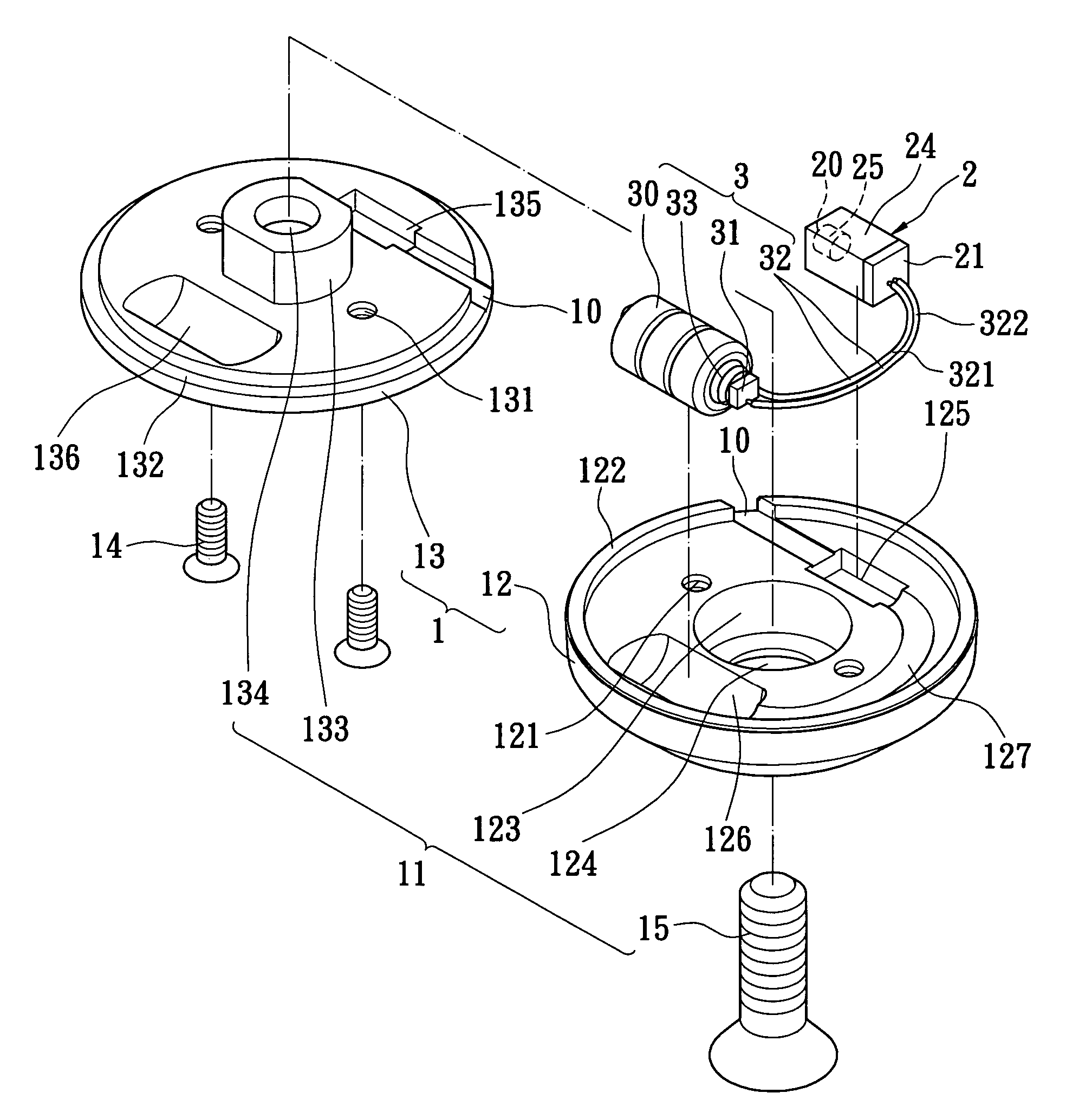
[0031]Please referring to FIG. 4˜6, the present invention is a laser alignment device of a circular saw machine, including a cover 1, a laser module 2 and a power control-supply unit 3.

[0032]The cover 1 defines a plurality of laser holes 10 on an edge of the cover 1 and a plurality of rectangular receiving slots 125, 135 therein; moreover, the cover further includes a fixing structure 11 for fixing the circular saw machine. The cover 1 includes a top cover 12 and a bottom cover 13, an inside of the top cover 12 is relative to an inside of the bottom cover 13. The top cover 12 has a plurality of screw bases 121 on an inside thereof, a bottom cover 13 defines a plurality of sinking holes 131 on an outside of the bottom cover 13 and a plurality of bolts 14 inserting into each of sinking holes 131 for locking the screw base. The top cover 12 has a protr...


PUM

PropertyMeasurementUnit
circumferenceaaaaaaaaaa
conductiveaaaaaaaaaa
conductive areaaaaaaaaaaa

Abstract

A laser alignment device of a circular saw machine includes a cover, a laser module, and a power control-supply unit. The cover defines a plurality of laser holes on a edge of the cover and a plurality of rectangular receiving slots. The laser module includes a rectangular base fixed in the rectangular receiving slot and a laser source-having a shooting portion corresponding to the laser hole. The power control-supply unit electrically connects to the laser module for simplifying parts and adding assembly speed.

Description

BACKGROUND OF THE INVENTION[0001](1) Field of the Invention[0002]The present invention relates to a laser alignment device of a circular saw machine and more particularly to a laser alignment device of a circular saw, wherein the laser alignment device is made use of assisting a circular saw cutter in aiming at a preparatory cutting line.[0003](2) Description of the Related Art[0004]A circular saw machine has a fast and straight feature that efficiently finishes a work of cutting. The kinds of circular saw machines include a manual circular saw machine that the circular saw is pushed to cut a cutting material fixed position and a table type circular saw machine that the cutting material is cut by the circular saw fixed position. Marking preparatory cutting line on the cutting material before starting to cut is for keeping the circular saw cutter on the preparatory cutting line. The laser alignment device is mounted in the circular saw cutter machine for assisting the circular saw cu...

Claims


Application Information

Patent Timeline
Patent Type & Authority Patents(United States)
IPC IPC(8): G02B27/20B23D59/00F21V7/04G01S1/00G09B9/00H01S3/00H01S3/30
CPCB23D59/003
Inventor TUNG, HSIN CHIH
Owner TUNG HSIN CHIH
Why Eureka
Try Eureka