

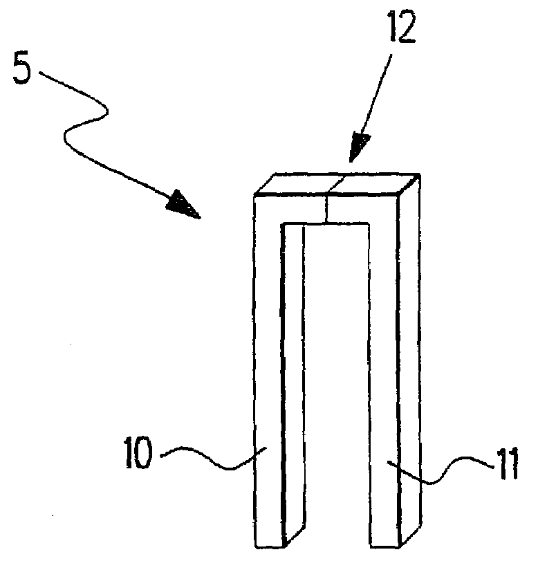
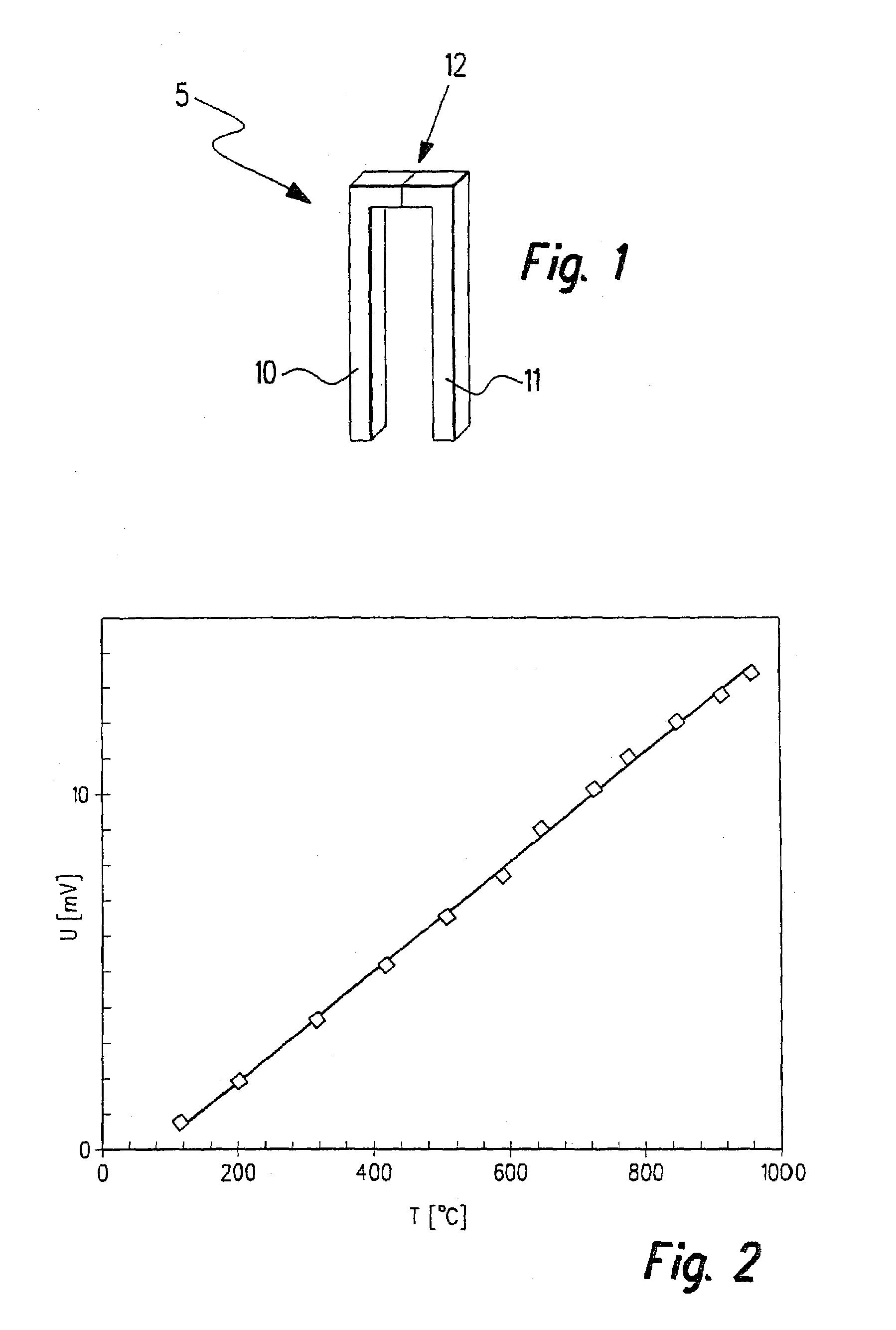
Thermoelectric component
a technology of thermoelectric components and components, applied in the manufacture/treatment of thermoelectric devices, instruments, heat measurement, etc., can solve the problems of increasing the material load capacity of the material with regard to temperature and application atmosphere, increasing the material load capacity of the material, etc., to achieve good thermoelectric voltage constancy, short response time, and good service life
- Summary
- Abstract
- Description
- Claims
- Application Information
AI Technical Summary
Benefits of technology
Problems solved by technology
Method used
Image

Examples
Embodiment Construction
[0015]The example embodiments further explained, first of all relate to polymeric precursor materials, provided with filler materials, which are convertible into ceramic materials by pyrolysis. Such precursor materials or filler materials, respectively, are described in European Published Patent Application No. 0 412 428 or in German Published Patent Application No. 195 38 695, which also describe that one may produce molded articles using pyrolysis, by the addition of filler materials to the polymeric precursor materials used. In this connection, the specific resistance of the ceramic molded articles obtained may be set both by the choice of the filler materials and by the choice of the polymeric precursor material.
[0016]As the polymeric precursor materials for the example embodiments which are further explained, polymers may be suitable which are convertible by pyrolysis into ceramic materials based on Si—C compounds, Si—C—N compounds, Si—Ti—C—O compounds, Si—C—O compounds, Si—B—C...
PUM
| Property | Measurement | Unit |
|---|---|---|
| temperature | aaaaa | aaaaa |
| temperature | aaaaa | aaaaa |
| temperature | aaaaa | aaaaa |
Abstract
Description
Claims
Application Information