
Blood pumping unit, with a coplanar disk inlet valve and an annular outlet valve

Inactive Publication Date: 2006-04-18
SORIN GRP ITAL SRL
View PDF26 Cites 124 Cited by
  • Summary
  • Abstract
  • Description
  • Claims
  • Application Information

AI Technical Summary

Benefits of technology

[0004]The aim of the present invention is to provide a pumping unit that has maximum constructive simplicity, so as to ensure modest costs and great reliability in operation. Within the scope of this aim, an object of the invention is to provide a pumping unit that is very compact and is suitable to be integrated easily with other devices that are present in the extracorporeal circuit through which the blood is meant to flow, such as for example a heat exchanger or an oxygenation apparatus.

Problems solved by technology

Known pulsating pumps are not entirely satisfactory, particularly with respect to the valves that regulate the inflow and outflow of the fluid.

Method used


Image

  • Blood pumping unit, with a coplanar disk inlet valve and an annular outlet valve
  • Blood pumping unit, with a coplanar disk inlet valve and an annular outlet valve
  • Blood pumping unit, with a coplanar disk inlet valve and an annular outlet valve

Examples


Embodiment Construction

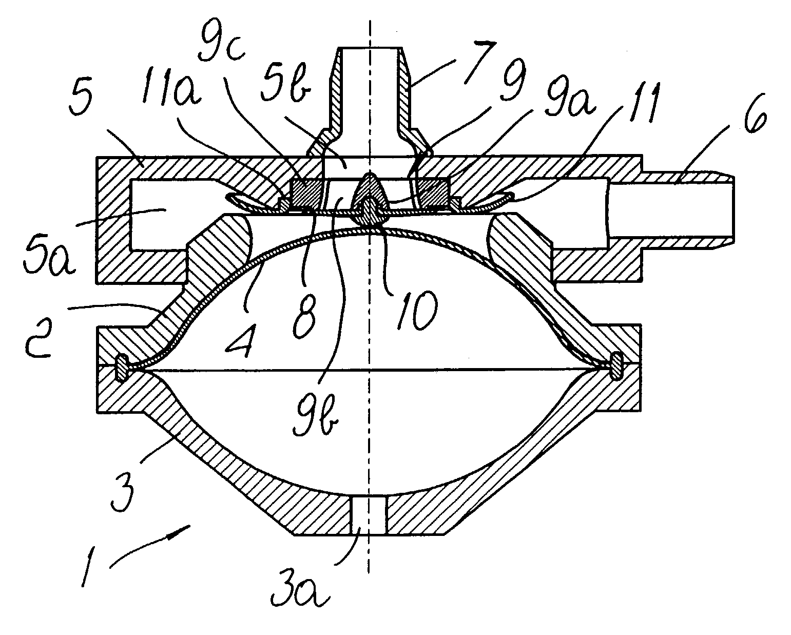
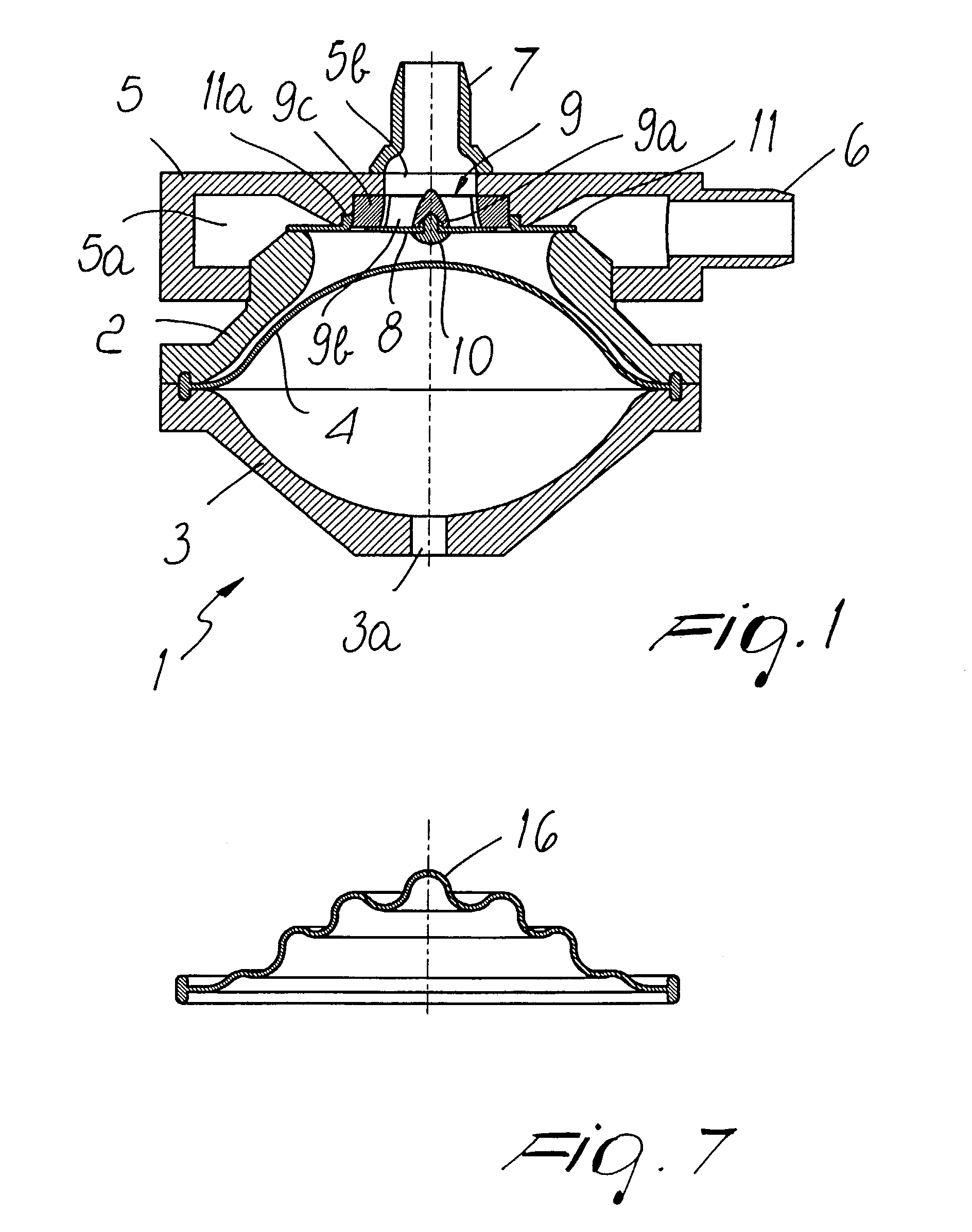
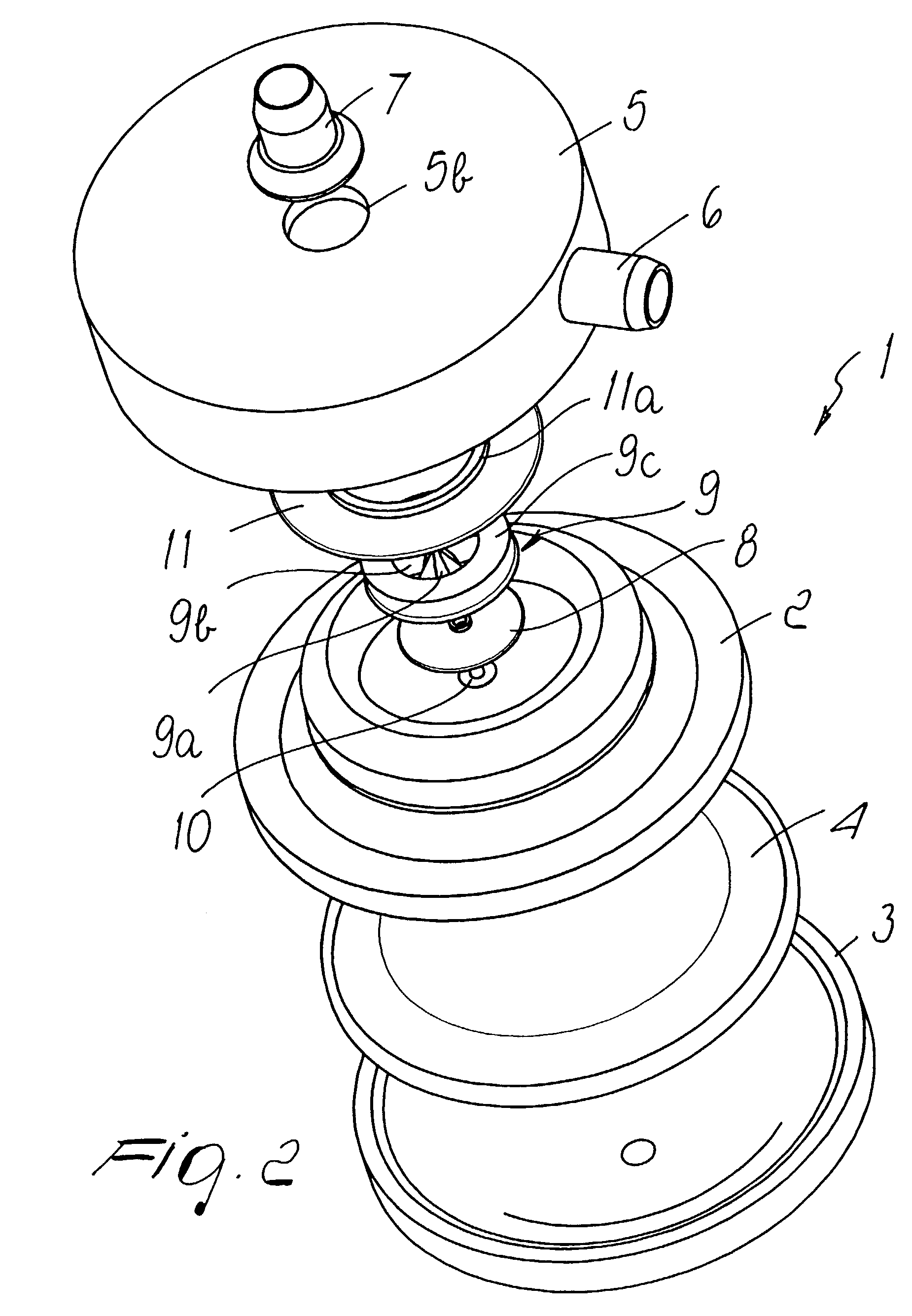
[0017]With reference to FIGS. 1 to 4, the numeral 1 generally designates the pumping unit provided with a body portion or enclosure that comprises two portions including a half-shell 2 and a second half-shell 3. The two half-shell portions define a pumping chamber 25 comprising an internal portion of space in which the elastic membrane or diaphragm 4 is arranged, dividing the space into two parts. The membrane is fixed around its perimeter at the joining plane of the two half-shells, which are rigidly connected by means of a film of adhesive.

[0018]The lower half-shell 3 is provided with a fluid port comprising hole 3a for connection to a line of working fluid, such as air, which is alternatively pressurized and depressurized. The frequency of the alternation of pressure and vacuum determines the rate at which fluid is pumped through the unit and may advantageously be selected to substantially coincide with the heart rate.

[0019]A discharge portion comprising ring 5 is monolithically ...


PUM


Abstract

A unit for pumping fluid, particularly blood, is provided with an enclosure that has two half-shells and an elastic membrane fixed perimetrically to the enclosure in order to divide its space into two parts. One of the half-shells is provided with valves that are located at the opening of two connecting ducts for the intake and delivery of the fluid, and the other half-shell is connected to a line of working fluid that is alternately pressurized and depressurized. The first valve is a disk-shaped sheet made of elastic material. The first valve is in a central position with a support that is fixed to the opening of the first duct for connection to the outside and is suitable to rest at its peripheral region on the support. A second valve is a sheet of elastic material located at the peripheral region of the disk at the opening of the second duct for connection to the outside which lies at the peripheral region of the opening of the first duct.

Description

FIELD OF THE INVENTION[0001]The present invention relates to a unit for pumping fluid, particularly blood.BACKGROUND OF THE INVENTION[0002]It is known that during many operations it is necessary to provide an extracorporeal circulation of blood in a circuit which includes a pump. One type of pump suitable for use in such extracorporeal circuits is a pulsating pump. The pulsating pump includes an enclosure suitable to contain a portion of space in which there acts an elastic membrane or diaphragm. The diaphragm is actuated by a working fluid acting against one face of the membrane which is alternatively pressurized and depressurized according to the heart rate and provides at the other face the suction and delivery of the blood.[0003]Known pulsating pumps are not entirely satisfactory, particularly with respect to the valves that regulate the inflow and outflow of the fluid.SUMMARY OF THE INVENTION[0004]The aim of the present invention is to provide a pumping unit that has maximum co...

Claims


Application Information

Patent Timeline
IPC IPC(8): F04B43/06A61M1/10A61M1/16
CPCA61M1/1037A61M1/1006A61M1/1698Y10T137/7838A61M60/113A61M60/43A61M60/892A61M60/894A61M60/38A61M60/851
Inventor MAIANTI, EDGARDO COSTAGHELLI, NICOLAPANZANI, IVO
Owner SORIN GRP ITAL SRL
Learn More