Implement for automatically milking a dairy animal

a technology for dairy animals and robot arms, applied in the field of automatic milking of dairy animals, can solve the problems that the movement of robot arms with teat cups towards teats does not always take place in a reliable manner, and achieve the effect of maximum of constructive simplicity and high resolution

Active Publication Date: 2014-08-19
MAASLAND
View PDF45 Cites 16 Cited by
  • Summary
  • Abstract
  • Description
  • Claims
  • Application Information

AI Technical Summary

Benefits of technology

[0010]By using such a matrix of receivers and by determining for these receivers, by means of the phase shifting of the emitted light, distances to the dairy animal, there is obtained per observation a complete, three-dimensional image of, for example, the teat. This three-dimensional image is in fact composed in one go, instead of by scanning. Moreover, it is not, or at least less than in the state of the art, distorted by movements of the entire dairy animal and / or its teat during the observation. Moreover, it is not necessary to move the robot arm to compose a complete image. As a result, there is a greater chance that the milking robot is moved in the right direction than in the case of EP0360354A1.
[0032]In a particular embodiment, the matrix with a plurality of rows and a plurality of columns of receivers, and advantageously also the radiation source, is arranged pivotably. This provides the advantage that for observing different parts of the dairy animal only the receiver device and, possibly, also the radiation source, has to be pivoted. This is in particular advantageous if the angle of view, and possibly also the angle of radiation, is relatively small, in order to ensure in this manner a relatively high resolution. Nevertheless it is also possible, of course, to connect the receiver device and the radiation source rigidly to the milking robot, or a component of the milking parlour, for a maximum of constructive simplicity.

Problems solved by technology

A drawback of the known milking implement is that moving the robot arm with teat cups towards the teat does not always take place in a reliable manner.

Method used


Image

  • Implement for automatically milking a dairy animal
  • Implement for automatically milking a dairy animal
  • Implement for automatically milking a dairy animal

Examples


Embodiment Construction

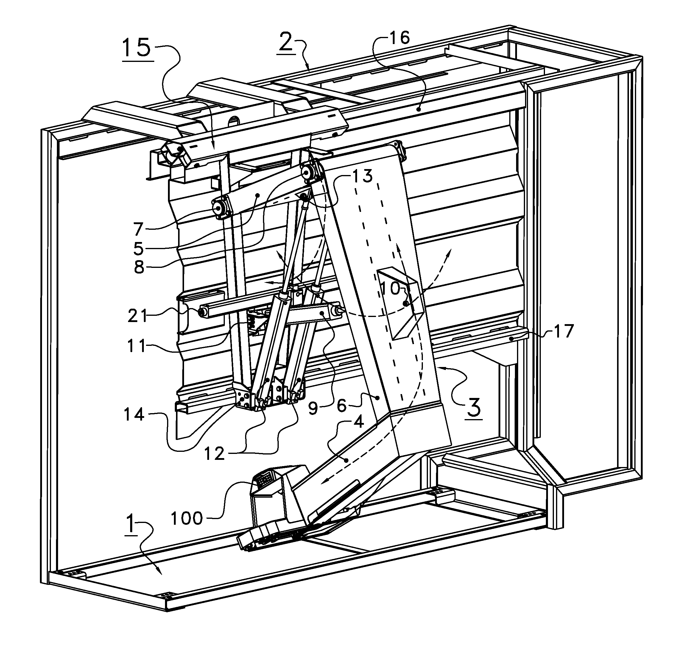
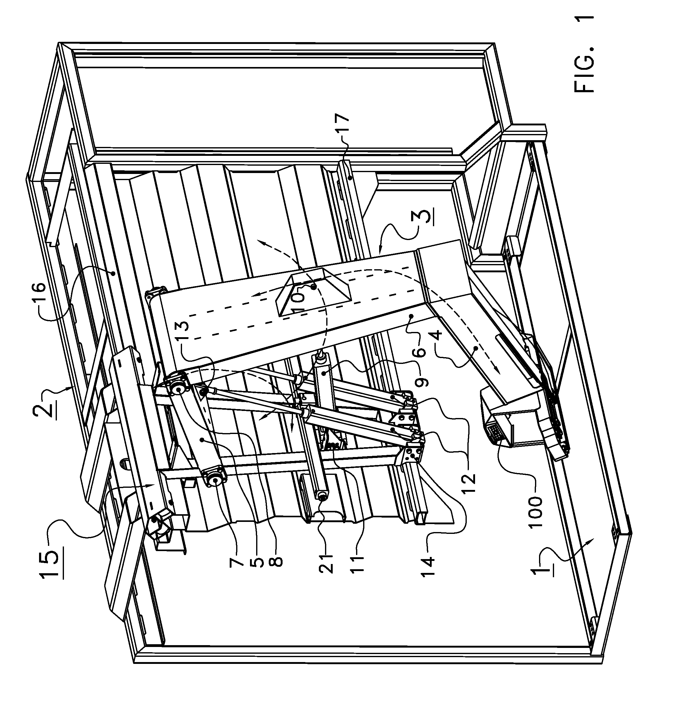
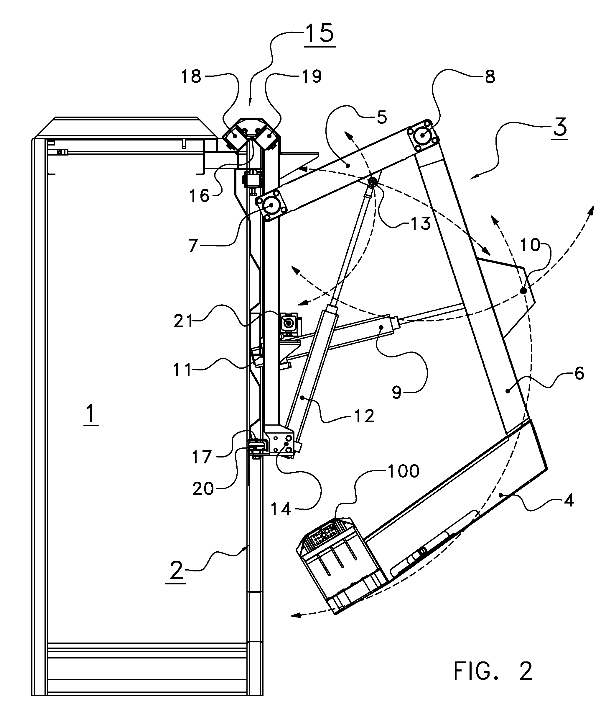
[0039]The following is a description of certain embodiments of the invention, given by way of example only and with reference to the drawings. The implement for automatically milking an animal, such as a cow, shown in a diagrammatic perspective view in FIG. 1, comprises a milking parlour 1 that accommodates one single animal, such as a cow. This milking parlour 1 is surrounded in a customary manner by a fencing 2 and is provided with an entrance door and an exit door which are, incidentally, not shown in the figures. In the milking parlour 1 and in the immediate vicinity thereof there is a milking robot comprising a robot arm construction 3 for automatically attaching a teat cup to a teat of an animal to be milked. The robot arm construction is provided with a robot arm 4 for carrying a teat cup, which robot arm 4 is pivotable to under the udder of the animal (see FIG. 3).

[0040]The robot arm construction 3 is provided with a first robot arm construction portion 5 and a second robot ...


PUM


Abstract

An implement for automatically milking a dairy animal, such as a cow, comprises a milking parlor, a sensor for observing a teat, and a milking robot for automatically attaching a teat cup to the teat. The milking robot comprises a robot control that is connected to the sensor. The sensor comprises a radiation source for emitting light, a receiver for receiving electromagnetic radiation reflected from the dairy animal, a lens, and sensor control unit. The sensor comprises a matrix with a plurality of rows and a plurality of columns of receivers. The sensor control unit is designed to determine for each of the receivers a phase difference between the emitted and the reflected electromagnetic radiation in order to calculate the distance from the sensor to a plurality of points on the part to be observed of the dairy animal.

Description

[0001]This application is a continuation of international application no. PCT / NL2007 / 000210, filed on Aug. 28, 2007, and claims priority from Netherlands application number 1032435 filed on Sep. 5, 2006. The contents of these applications are hereby incorporated by reference in their entirety.BACKGROUND OF THE INVENTION[0002]1. Field of the Invention[0003]The present invention relates to an implement for automatically milking a dairy animal, such as a cow.[0004]2. Description of the Related Art[0005]European patent EP0360354A1 discloses an implement for automatically milking a cow, which is provided with a robot arm. At an end of the robot arm there is provided a sliding element that is movable relative to the robot arm. At the same end of the robot arm there are provided holders for four teat cups. Each of the teat cups may be connected to a vertically movable cylinder by means of a magnetic coupling. The robot arm is movable and is capable of being brought with the teat cups to un...

Claims


Application Information

Patent Timeline
Patent Type & Authority Patents(United States)
IPC IPC(8): A01J3/00A01J5/00
CPCG01S17/88A01J5/0175Y10S901/09Y10S901/46A01J5/017G01S17/42
Inventor VAN, DEN, BERG, KAREL
Owner MAASLAND
Why Eureka
Try Eureka