Pacifier

a pacifier and pacifier technology, applied in the field of pacifiers, can solve the problem of slight inclination of the wing, and achieve the effect of preventing any suction for

Inactive Publication Date: 2006-04-18
DAVIS JOHN J
View PDF15 Cites 56 Cited by
  • Summary
  • Abstract
  • Description
  • Claims
  • Application Information

AI Technical Summary

Benefits of technology

[0010]It is therefore an object of the invention to provide a pacifier that avoids the problems mentioned above. It is also an object of the invention to provide a pacifier that prevents any suction force between the palate and the pacifier as well as the palate and the tongue.
[0012]Pressure on the nipple by the infant's tongue can cause the wings to pivot apart slightly. The open channel prevents the vacuum pressure commonly caused by conventional nipples to prevent damage to the palate and thus prevent bite abnormalities in the infant's mouth, or malocclusion. The open channel has a curved shape such that at least a portion of each wing contacts the midline of the palate. In the alternative, the open channel may be straight but since the wings spread only slightly, at least a portion of each wing contacts contact the middle section of the palate that, for purposes of this specification, is defined as the middle third section of the palate flanking the midline of the palate.

Problems solved by technology

Pressure on the nipple by the infant's tongue can cause the wings to pivot apart slightly.

Method used


Image

  • Pacifier
  • Pacifier
  • Pacifier

Examples


first embodiment

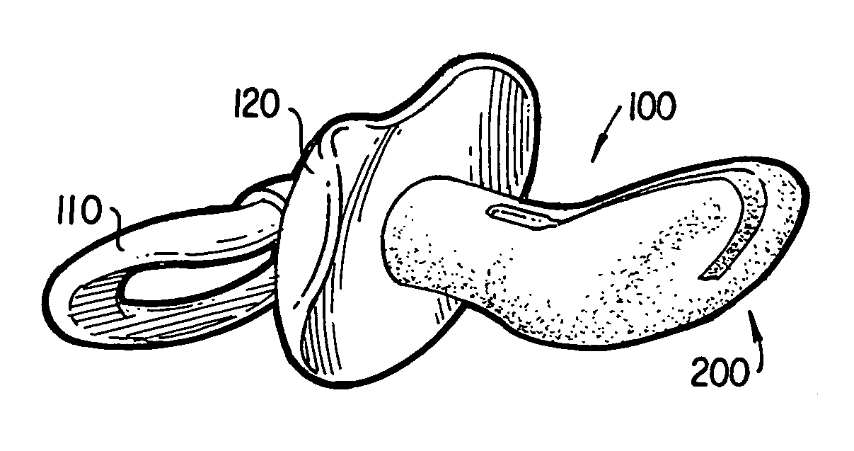
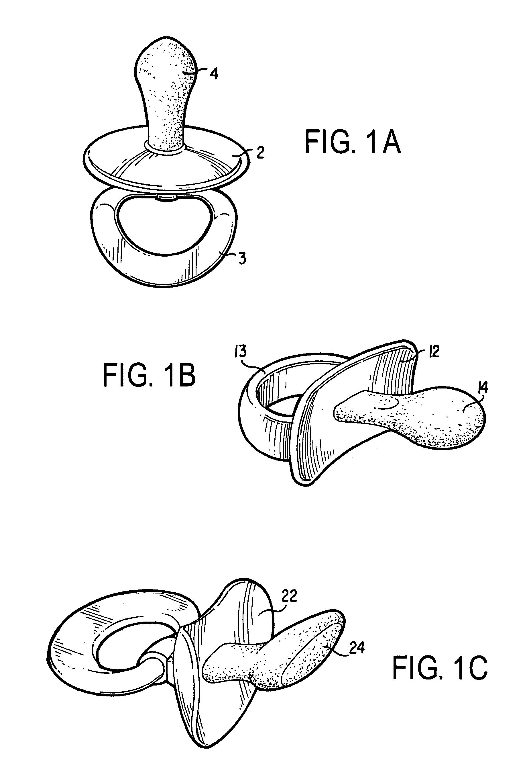
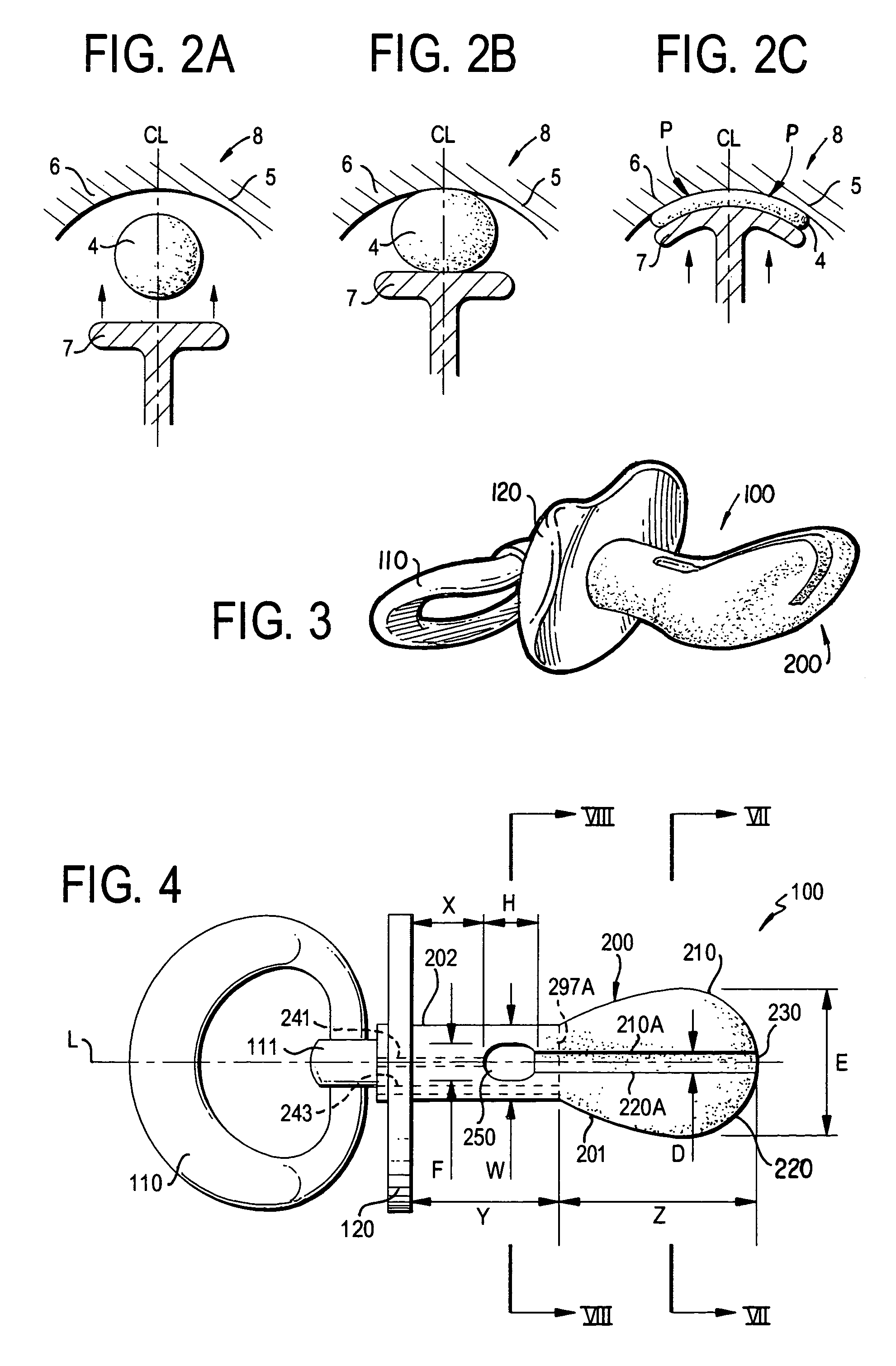
[0040]the invention is shown in FIGS. 3–6. A pacifier 100 has a ring 110 for holding the pacifier, a shield 120 and a nipple 200 shown lying at least partly along a longitudinal axis “L”. Ring 110 generally has a circular shape which is threaded through a post 111, however, any structure that allows for grabbing pacifier 100 without having to contact nipple 200 would work sufficiently. Ring 110 and post 111 may also be replaced entirely by a simple rod handle design, such as rod handle 3 of FIG. 1A or a wider version of the rod, such as handle 13 shown in FIG. 1B.

[0041]Shield 120 as shown in FIGS. 3–6 has a flat shape, however, the concave or convex shapes shown in FIGS. 1A–1C would also work.

[0042]As shown in FIGS. 3–5, nipple 200 has a generally bulbous shape extending away from shield 120. It comprises a stem portion 202 and a larger rounded head portion 201. In use of the pacifier 100, a baby places its lips around stem portion 202 of nipple 200 and in an abutting relationship w...

embodiment 400

[0054]FIG. 5E shows an embodiment 400 having the same general structure as the embodiment of FIG. 5 but a transverse hole 250A extends from an opening on the upper side top of the stem portion 202 far enough to communicate with a vent passageway 241A of the stem portion 402, but does not extend completely through the stem portion 402.

[0055]A sucking action using pacifier 100 is shown in FIGS. 9A–9C. Nipple 200 is placed into an infant's mouth, between a palate 8 having two ridges 5 and 6 about a center line CL and a tongue 7, which is shown in FIG. 9A. As tongue 7 moves upward during a sucking action, nipple 200 is compressed between the tongue and palate 8. The compression of nipple 200 causes wings 210 and 220 to expand outwardly away from channel 230, increasing the channel width that allows the air between palate 8 and nipple 200 to move into and out of channel 230. Upon full compression of nipple 200, as shown in FIG. 9C, the width of channel 230 is a maximum. The movement of a...


PUM


Abstract

A pacifier includes a nipple, a shield and a handle. The nipple comprises a pair of wings extending longitudinally along a bulbous end of the nipple. The wings allow for air to exit and enter the space between the palate and the nipple to prevent a vacuum therebetween. Alternatively, the nipple has a channel system comprising a series of holes on the surface of the nipple, some contacting the palate, to also allow the air to enter and exit the space between the palate and the nipple. The stem of the nipple may also have a transverse hole which receives the baby teeth to prevent an open bite.

Description

FIELD OF THE INVENTION[0001]The principal utility of the invention relates to pacifiers for infants who still have the natural sucking instinct or urge.BACKGROUND OF THE INVENTION[0002]From birth, infants have a natural sucking instinct or urge. This phenomenon is essential for the infants' survival, for it allows them to feed from the infant's mother's breast a short time following birth. However, if the sucking urge is not gratified, the infant will generally have a remaining urge that may lead either to frustration if the urge is not satisfied or the infant will lose the urge. A common practice to ease the frustration of the sucking urge is for the infant to engage in a non-nutritional sucking where the infant will suck a thumb, finger, or pacifier. Such acts may satisfy the urge. As a result of the satisfaction, such acts may provide a source of pleasure, self-gratification, comfort, and soothing relaxation. As the infant grows, the sucking urge is gradually replaced by masticat...

Claims


Application Information

Patent Timeline
Patent Type & Authority Patents(United States)
IPC IPC(8): A61J17/00
CPCA61J17/00A61J11/007A61J17/001A61J17/107
Inventor DAVIS, JOHN J.
Owner DAVIS JOHN J
Why Eureka
Try Eureka