Duplexer having two surface acoustic wave filters on one substrate

a surface acoustic wave and duplexer technology, applied in the field of duplexers, can solve the problems of increased crosstalk between transmission signals and reception signals, reduced stop-band suppression, and difficult production of 1.9 ghz band antenna duplexers utilizing saw filters, and achieve excellent filter characteristics

Active Publication Date: 2006-04-18
TAIYO YUDEN KK
View PDF10 Cites 31 Cited by
  • Summary
  • Abstract
  • Description
  • Claims
  • Application Information

AI Technical Summary

Benefits of technology

[0012]A more specific object of the present invention is to provide a duplexer that has two or more SAW filters on a single substrate and exhibits excellent filter characteristics.

Problems solved by technology

However, two SAW filters formed on a small substrate in an attempt to produce a smaller device cause problems such as a decrease in the degree of stop-band suppression and an increase in crosstalk between transmission signals and reception signals.
These problems are conspicuous especially in 1.9 GHz band antenna duplexers than in 800 MHz band antenna duplexers, and for this reason, it has been difficult to produce 1.9 GHz band antenna duplexers utilizing SAW filters.
As a result, the gap between the center frequencies fluctuate by twice as much as the fluctuation of the center frequency of each SAW filter, causing large variations in the characteristics of antenna duplexers.
If both of the demands are to be met, however, the crosstalk between transmission signals and reception signals increases.
Therefore, it has been very difficult to achieve good filter characteristics.

Method used


Image

  • Duplexer having two surface acoustic wave filters on one substrate
  • Duplexer having two surface acoustic wave filters on one substrate
  • Duplexer having two surface acoustic wave filters on one substrate

Examples


first embodiment

(First Embodiment)

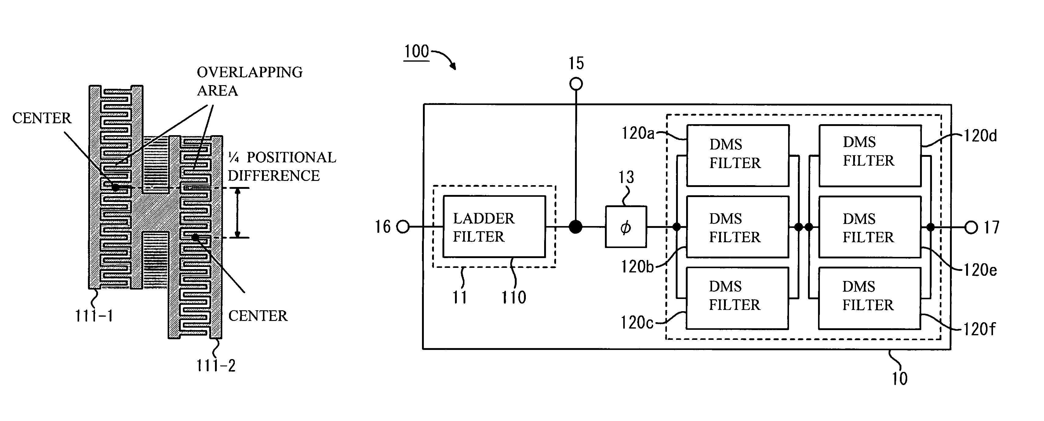
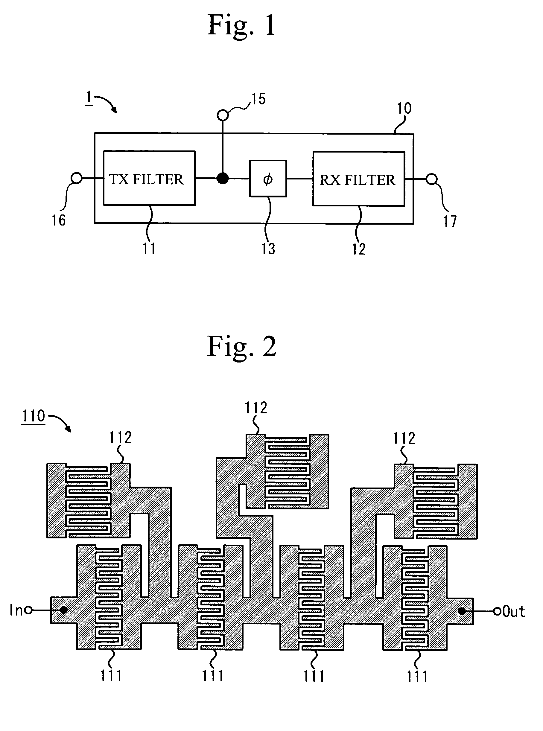
[0040]A first embodiment of the present invention will be first described in detail. FIG. 1 is a block diagram illustrating the structure of a duplexer 1 in accordance with this embodiment. The duplexer 1 has surface acoustic wave (SAW) filters (a transmission filter 11 and a reception filter 12) formed on a substrate 10. A phase shifter 13 that is a matching circuit for matching input impedances is provided between the two SAW filters 11 and 12, i.e., the phase shifter 13 is provided on the line that connects the SAW filters 11 and 12 to an antenna port 15 serving as a common terminal of the SAW filters 11 and 12.

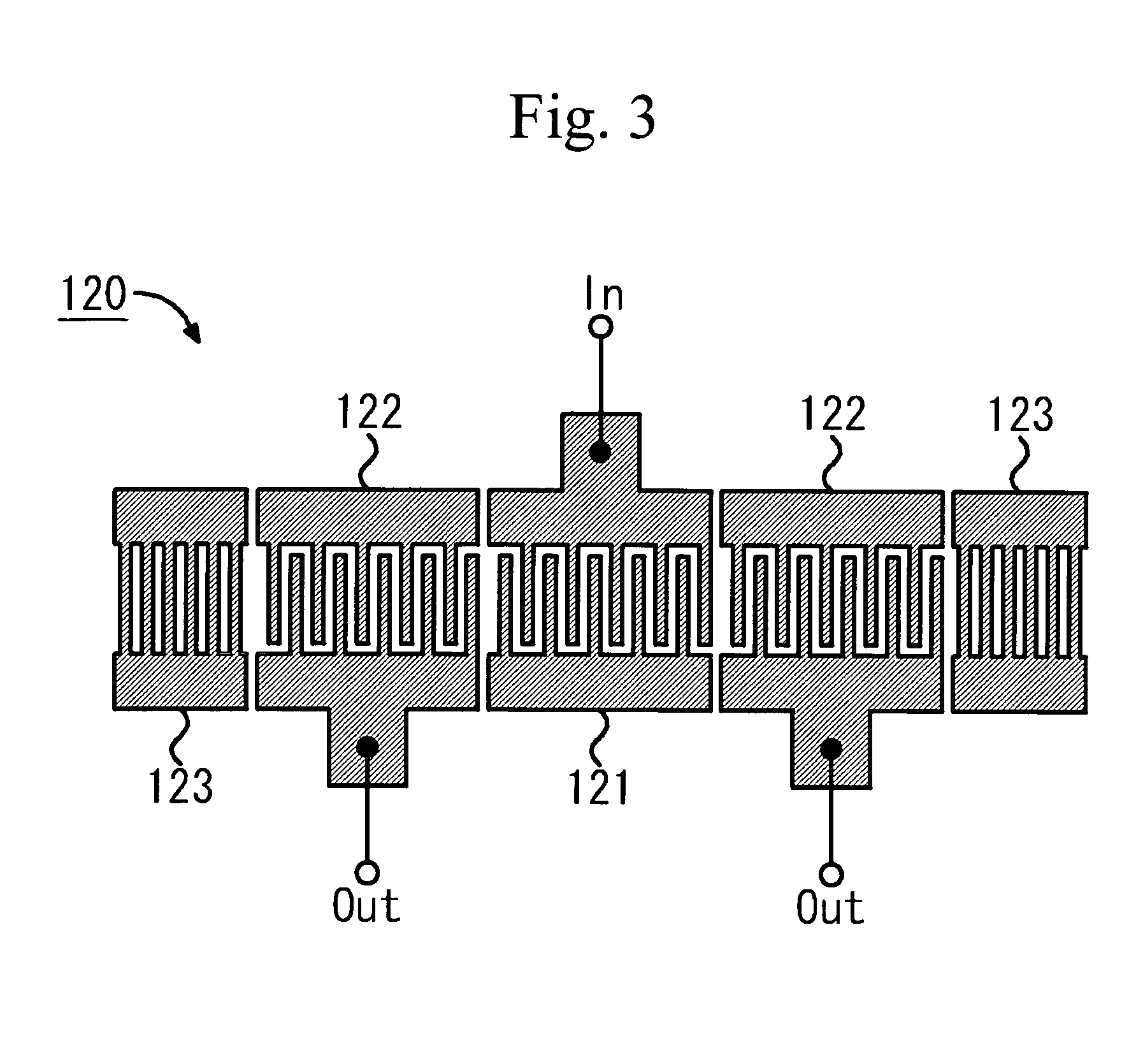
[0041]In this embodiment, both of the two filters 11 and 12 may be ladder filters, or one of the two filters 11 and 12 may be a coupled multi-mode filter. In the following embodiments, the transmission filter 11 is embodied by a ladder filter 110 shown in FIG. 2, and the reception filter 12 is embodied by a double-mode SAW (hereinafter referred to as DMS)...

second embodiment

(Second Embodiment)

[0070]Referring now to FIG. 18, a second embodiment of the present invention will be described in detail. FIG. 18 is a top view of a SAW device chip 20A of a duplexer in accordance with this embodiment. In the SAW device chip 20A, the surface having two SAW filters 11 and 12 formed thereon is regarded as the upper surface.

[0071]As shown in FIG. 18, the SAW device chip 20A of this embodiment has the same structure as the SAW device chip 10A of the first embodiment, except that a ground electrode 210 that is grounded is formed in a region sandwiched by the transmission filter 11 and the reception filter 12.

[0072]In a case where the IDTs 111 and 112 of the transmission filter 11 and the IDTs 121 and 122 of the reception filter 12 are formed on the same surface of the substrate 10 like the structure of this embodiment and the first embodiment, current leakage might be caused between the transmission filter 11 and the reception filter 12 through the substrate 10. As a ...

third embodiment

(Third Embodiment)

[0076]A third embodiment of the present invention will now be described in detail. As in the first embodiment, the transmission filter 11 is the ladder filter 110 in this embodiment, and the reception filter 12 is the DMS filter 120 in this embodiment. In the first embodiment described above, each of the IDTs 111, 112, 121, and 122 of the transmission filter 11 and the reception filter 12 is a single-layer structure made of an electrode material mainly containing aluminum (Al).

[0077]Generally, it is preferable to form the IDTs 111 and 112 of the transmission filter 11 with electrode films having high power durability, because larger power is normally applied to the transmission filter 11 than to the reception filter 12. In view of this, the IDTs 111 and 112 are formed with electrode films having relatively high power durability in this embodiment.

[0078]More specifically, examples of electrode films having high power durability include metallic films each having a t...


PUM


Abstract

A duplexer includes two surface acoustic wave filters that are formed on one substrate, at least one of the two surface acoustic wave filters being a ladder filter. In this duplexer, the positional difference between the centers in the surface acoustic wave propagating direction of each two neighboring comb-like electrodes among comb-like electrodes that form series-arm resonators in the ladder filter is equal to or smaller than a fourth of the length in the propagating direction of the comb-like electrode having the larger number of pairs of electrode fingers of each two neighboring comb-like electrodes.

Description

BACKGROUND OF THE INVENTION[0001]1. Field of the Invention[0002]The present invention generally relates to duplexers, and more particularly, to a duplexer utilizing surface acoustic wave filters.[0003]2. Description of the Related Art[0004]Antenna duplexers each having two surface acoustic wave (SAW) filters are used for mobile communication devices, especially for 800 MHz band portable telephone devices today. These SAW filters used for antenna duplexers are required to have high power durability to perform stable operations and achieve long lives. Accordingly, the two filters of each duplexer have normally been formed with ladder filters that have SAW devices connected in a ladder-like fashion and exhibit relatively high power durability.[0005]As there has been an increasing demand for smaller-sized portable telephone devices and mobile communication devices, SAW filters that can be relatively easily made smaller in size are preferred for antenna duplexers used for 1.9 GHz band mo...

Claims


Application Information

Patent Timeline
Patent Type & Authority Patents(United States)
IPC IPC(8): H03H9/00H01L41/09H01L41/18H03H9/145H03H9/25H03H9/64H03H9/72
CPCH03H9/0038H03H9/0576H03H9/725H03H9/72H03H9/6483
Inventor TSUTSUMI, JUNINOUE, SHOGOMATSUDA, TAKASHIUEDA, MASANORI
Owner TAIYO YUDEN KK
Why Eureka
Try Eureka