
Blade cleaner cartridge with dust and lint seal blade

a cleaning blade and seal blade technology, applied in the direction of electrographic process equipment, instruments, optics, etc., can solve the problems of not being able to foolproofly remove the scavenged particulate material from the sump blade without some potential for blowing the particles throughout the machine frame, and still exist in certain respects, so as to reduce the effect of oil contamination, reduce internal dusting, and be convenient to mount into the cleaning blad

Inactive Publication Date: 2006-04-18
EASTMAN KODAK CO
View PDF9 Cites 15 Cited by
  • Summary
  • Abstract
  • Description
  • Claims
  • Application Information

AI Technical Summary

Benefits of technology

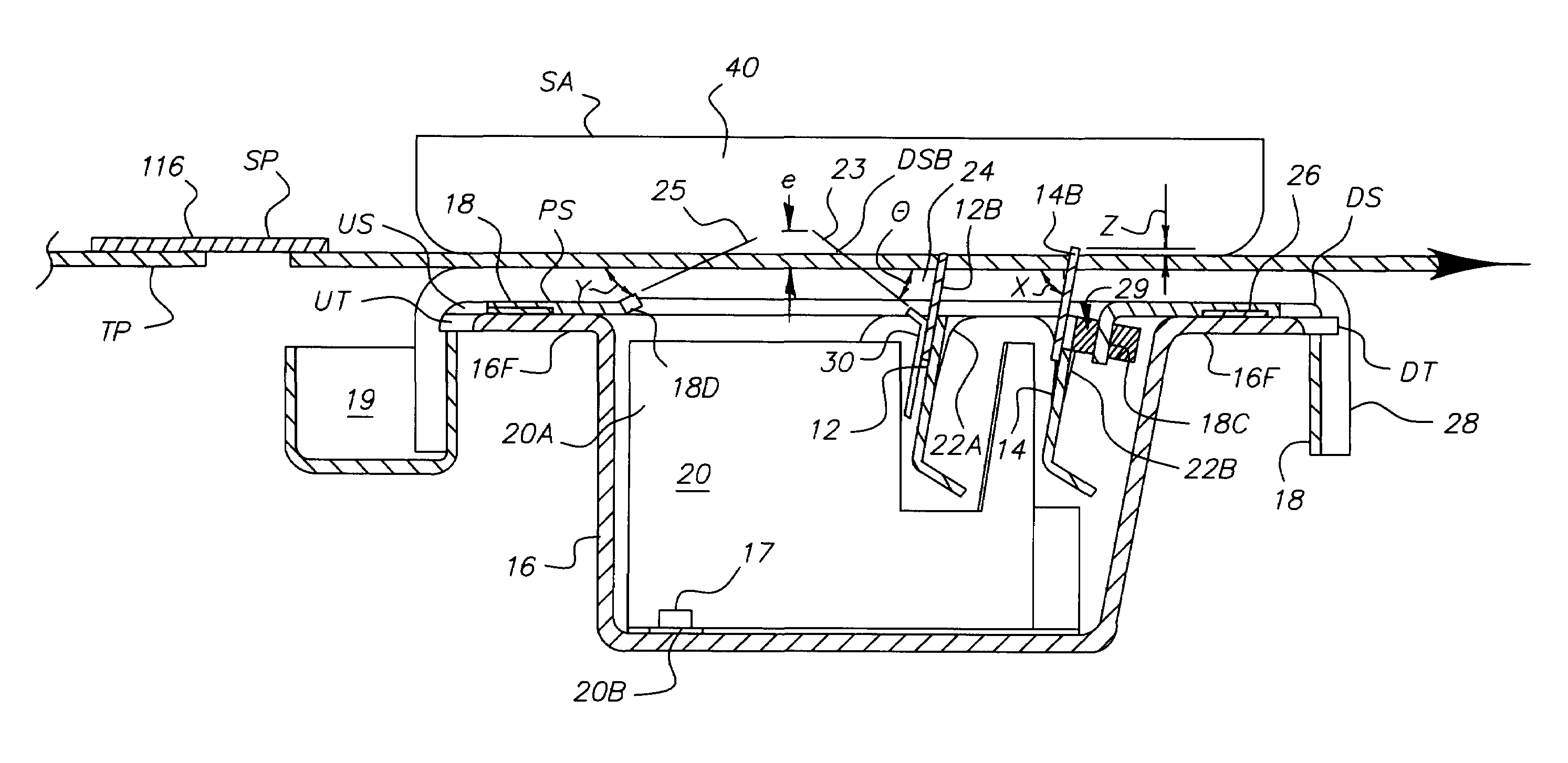
[0011]The present invention addresses the shortcomings within the prior art by providing a dust seal blade assembly which is easily mounted into a cleaning blade to reduce internal dusting in a cleaner and for trapping of lint, paper dust or fibrous material and which might also reduce the effects of oil contamination.
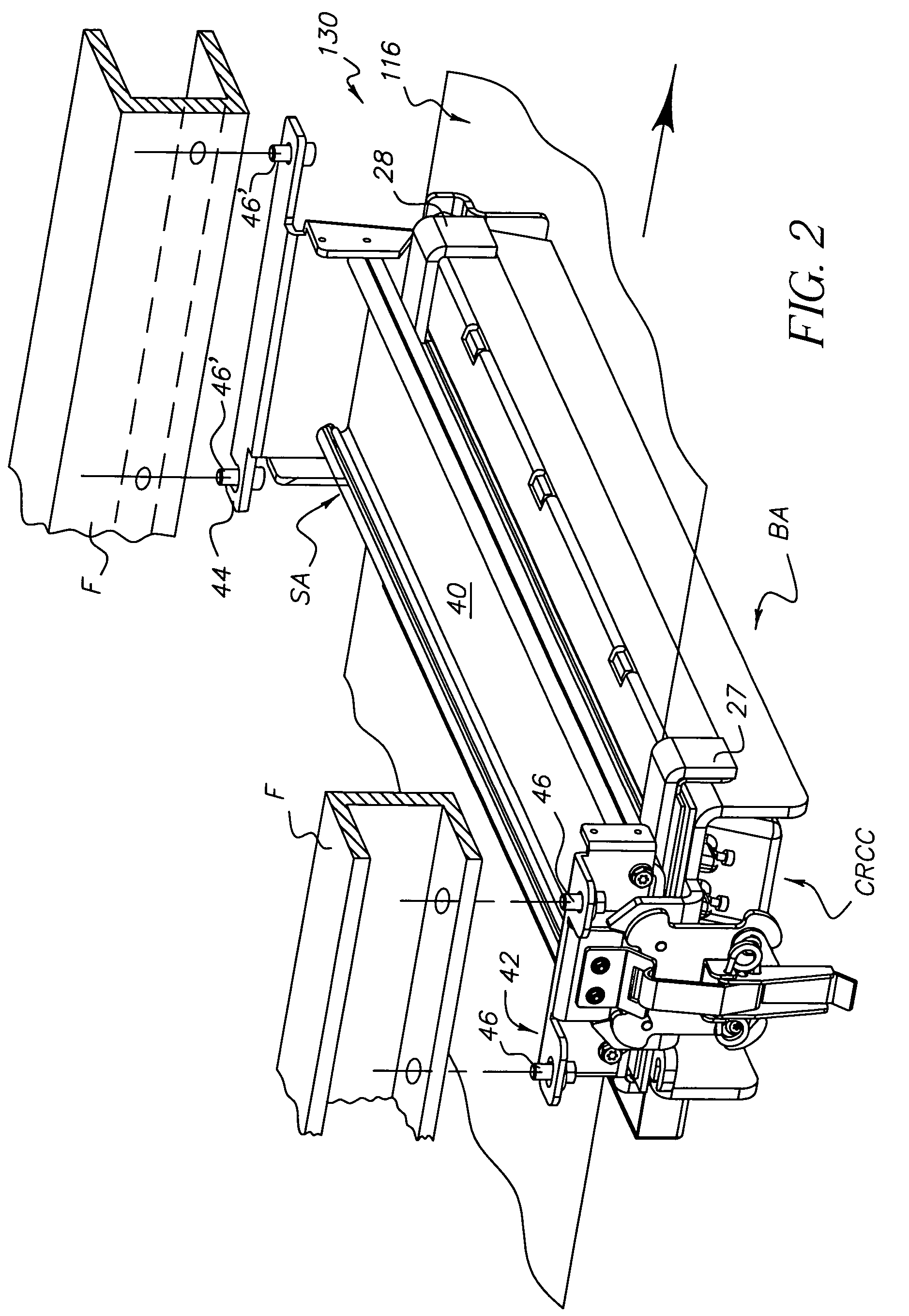
[0012]An object of the invention is to provide a relatively low-cost, operator-replaceable cartridge comprising one or more wiper blades with at least one of them having the dust seal blade assembly and enclosed within a particle sump assembly that is easily removed from a printer / copier.
[0013]It is an additional object of the invention, to provide a sump assembly in the form of a cartridge that can be serviced away from the machine or, alternatively, discarded and replaced with a new cartridge and that can be easily serviced for worn out parts, remanufactured or recycled.

Problems solved by technology

The cleaning station disclosed in U.S. Pat. No. 4,866,483 provides certain advantages that were not found previously within the prior art, however, problems still exist in certain respects.
For example, the sump housing that receives the toner that has been wiped from the belt surface by the blade cleaners is relatively small, thereby requiring the relatively costly auger system to continuously transport particles to a remote location for storage prior to removal.
Furthermore, while ready access may be gained to the cleaning station by simply pivoting the print engine frame to its open position, there is no fool-proof way of removing the scavenged particulate material from the sump blade without some potential for blowing the particles throughout the machine frame.
Also, since there is no lid or cover on the top of the sump, scavenged particles can escape the sump and contaminate the machine elements while the machine is in operation.
Moreover, since there is no hard backup for the web to resist the pressure applied by the cleaning blades, the web is likely to stretch over time, changing the dynamics at the blade edge / web interface.
U.S. Pat. No. 6,453,134, in the names of Ziegelmuller, et al., issued Sep. 17, 2002, discloses an improved blade cleaner having a lid to isolate the removed scavenged particles so that they can not escape the sump and contaminate the machine elements while the machine is in operation, however, U.S. Pat. No. 6,453,134 does not disclose any techniques for simple and easy removal and replacements of the sump assembly.
Additionally, U.S. Pat. No. 5,991,568 discloses a few techniques for implementing the dust seal blade with a cavity, however, U.S. Pat. No. 5,991,568 does not address the issues presented in a wiper blade configuration.
Additionally, the wiper blade embodiments are difficult to implement and require further robustness for lint removal than is afforded by a dual blade cleaner approach discussed above.

Method used


Image

  • Blade cleaner cartridge with dust and lint seal blade
  • Blade cleaner cartridge with dust and lint seal blade
  • Blade cleaner cartridge with dust and lint seal blade

Examples


Embodiment Construction

[0030]The preferred embodiment, as described herein, is not intended to disclose all possible variations of the invention, and it should be understood that the described embodiments are only examples of the invention. The scope of the invention is determined by the appended claims. The cleaning apparatus of the invention is adapted for use in an electrostatic printing machine to clean marking particles (toner) and other particulate material. The invention is particularly well adapted for systems employing an endless web used to transport image-receiver sheets. It will be evident from the ensuing description that the invention is equally well suited for use in a wide variety of devices to clean particulate material from different types of moving surfaces.

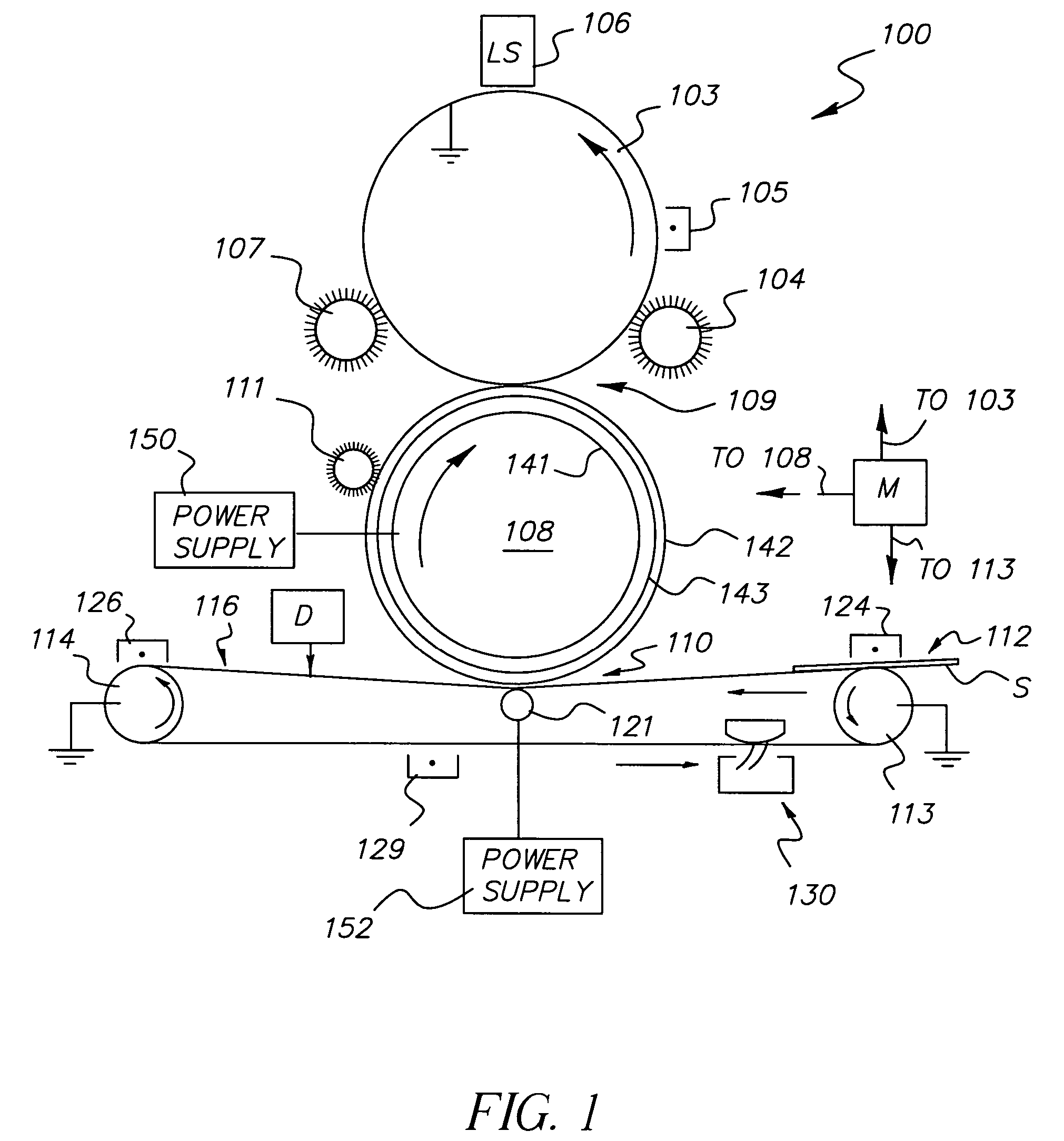
[0031]Referring to FIG. 1, an exemplary electrophotographic document printer 100 is shown having a primary image-forming member 103, for example, a rotatably driven conductive drum having an outer surface of a photoconductive materia...


PUM


Abstract

In an apparatus for cleaning particulates from a moving web, a dust seal blade assembly which is easily mounted to a cleaning blade to reduce internal dusting in a cleaner apparatus and for trapping of lint, paper dust, or fibrous material and which might also reduce the effects of oil contamination. The arrangement provides a low-cost, operator-replaceable cartridge having one or more wiper blades with at least one of them having the dust seal blade assembly and enclosed within a particle sump assembly that is easily removed from association with the web being cleaned.

Description

CROSS-REFERENCE TO RELATED APPLICATION[0001]Reference is made to the following commonly assigned application, the disclosure of which is incorporated herein by reference:[0002]U.S. patent application Ser. No. 10 / 625,423, filed on Jul. 23, 2003 (U.S. Publication Number 2004-0120728-A1, published on Jun. 24, 2004), in the names of Francisco L. Ziegelmuller, et al., entitled: WEB-CLEANING APPARATUS FOR ELECTROSTATIC PRINTER / COPIER, now abandoned.FIELD OF THE INVENTION[0003]This invention relates generally to improvements in cleaning apparatus of the type used, for example, in electrostatic document printers or copiers to remove residual toner, carrier, dust, lint, paper fibers and the like from a moving surface, typically in the form of an endless web or drum.BACKGROUND OF THE INVENTION[0004]There are numerous cleaning devices that have been employed within the electrographic industry for copier and printer apparatus to remove particulate material, such as toner, carrier, dust, lint, p...

Claims


Application Information

Patent Timeline
Patent Type & Authority Patents(United States)
IPC IPC(8): G03G21/00
CPCG03G21/0011
Inventor ZIEGELMULLER, FRANCISCO L.DUNN, CAROL K.CARRONE, MARIA B.BROWN, KENNETH J.ANDERSON, DOUGLAS C.
Owner EASTMAN KODAK CO
Learn More