Methods and systems for detecting noise in a position sensor using minor shifts in sensing frequency

a technology of position sensor and sensing frequency, applied in the field of methods, can solve the problems of long-term problems in identifying and reducing the effect of noise on the sensor, difficult to identify or filter out, and difficult to remove noise components

Active Publication Date: 2006-04-18
SYNAPTICS INC
View PDF8 Cites 178 Cited by
  • Summary
  • Abstract
  • Description
  • Claims
  • Application Information

AI Technical Summary

Problems solved by technology

In particular, difficulties have long been realized in identifying and reducing the effects of noise upon the sensor.
Although many sensors now include low and / or high-pass filters that can effectively remove many types of noise, problems remain in identifying and removing noise components with frequencies that are close to the sensor sensing frequency or any of its harmonics.
So called “tuned noise” is difficult to identify or filter out because the effective “beat” frequency of the tuned noise is often very close to the frequency of signals resulting from the user-applied stimulus itself, causing the tuned noise to appear as a stimulus applied to the sensing region.
As a result, distinguishing the effects of undesirable tuned noise from the desirable effects of the stimulus can be quite difficult.
This technique has several disadvantages, however, in that determining whether the stimulus is present at any given time can be difficult in practice, particularly in the presence of significant external noise.
Moreover, because this technique measures noise only when the stimulus is not present, sources of noise present within the stimulus itself (e.g. environmental radio frequency noise coupled to the sensor via the stimulus) are not considered.
While this technique does measure noise coupled to the sensor via the stimulus, it does not address the issue of low beat frequencies.
Further, the complexities introduced by disabling the sensing function can be relatively difficult and / or expensive to implement in practice.

Method used


Image

  • Methods and systems for detecting noise in a position sensor using minor shifts in sensing frequency
  • Methods and systems for detecting noise in a position sensor using minor shifts in sensing frequency
  • Methods and systems for detecting noise in a position sensor using minor shifts in sensing frequency

Examples


Embodiment Construction

[0012]The following detailed description is merely exemplary in nature and is not intended to limit the invention or the application and uses of the invention. Furthermore, there is no intention to be bound by any expressed or implied theory presented in the preceding technical field, background, brief summary or the following detailed description.

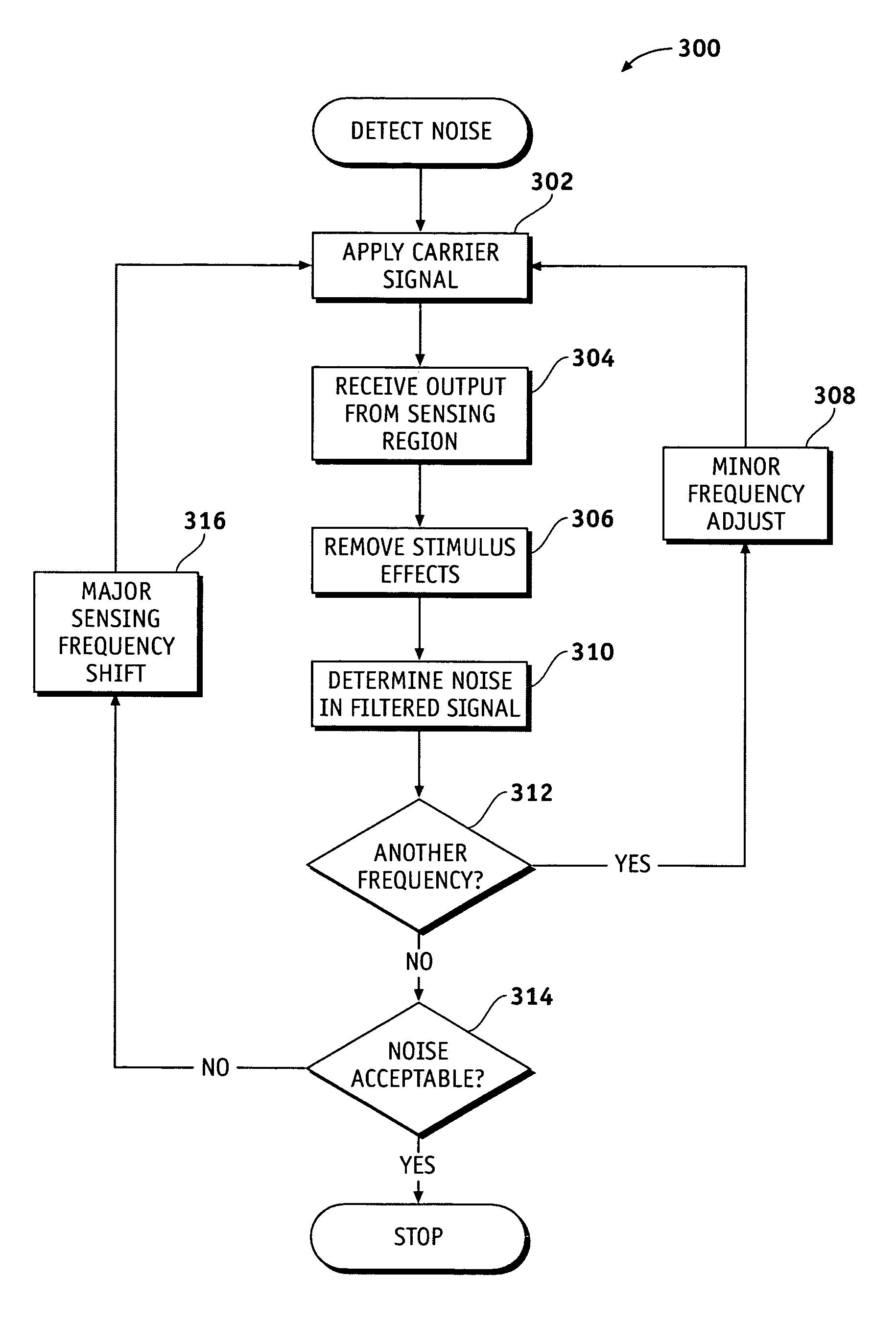
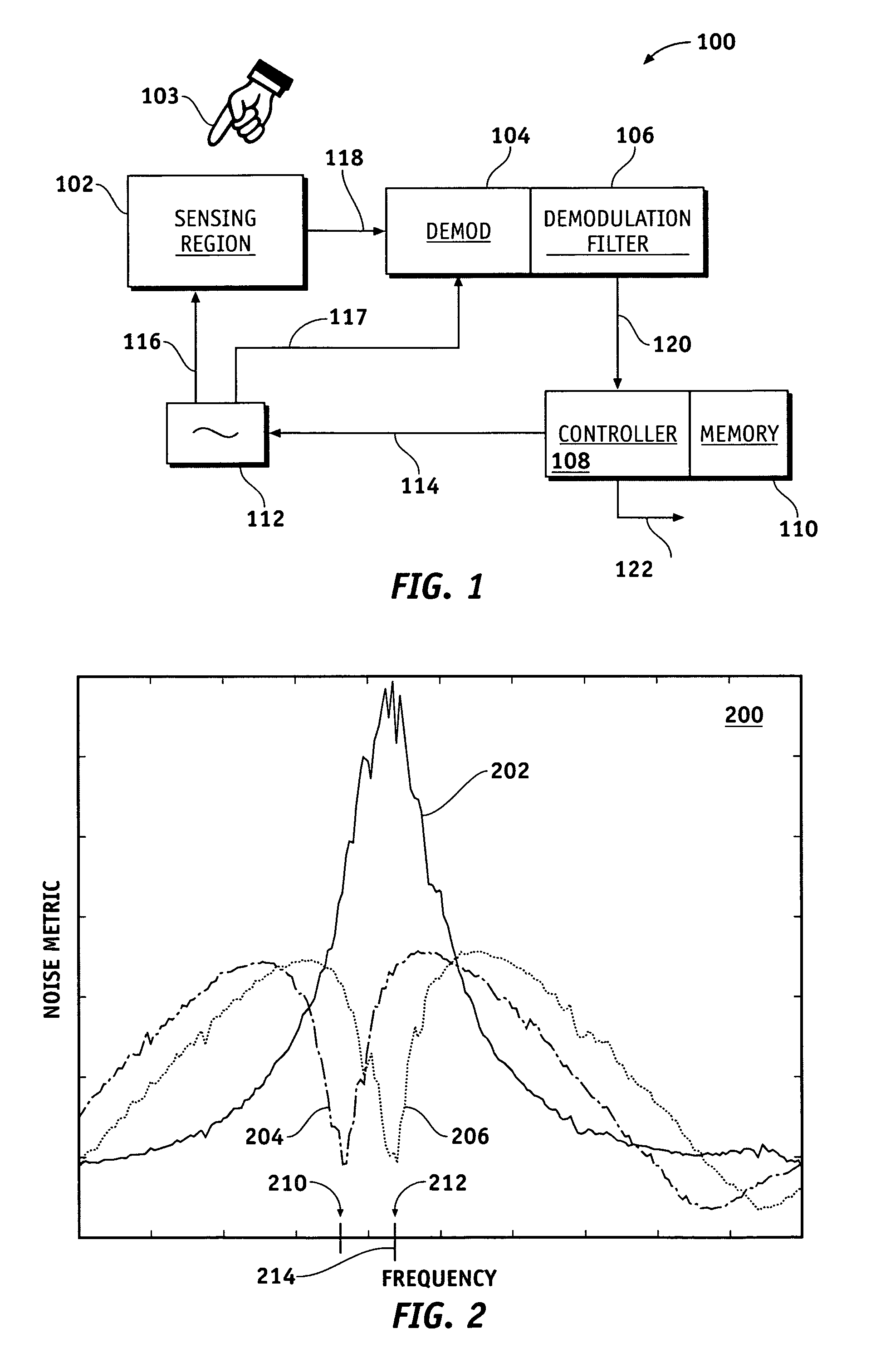
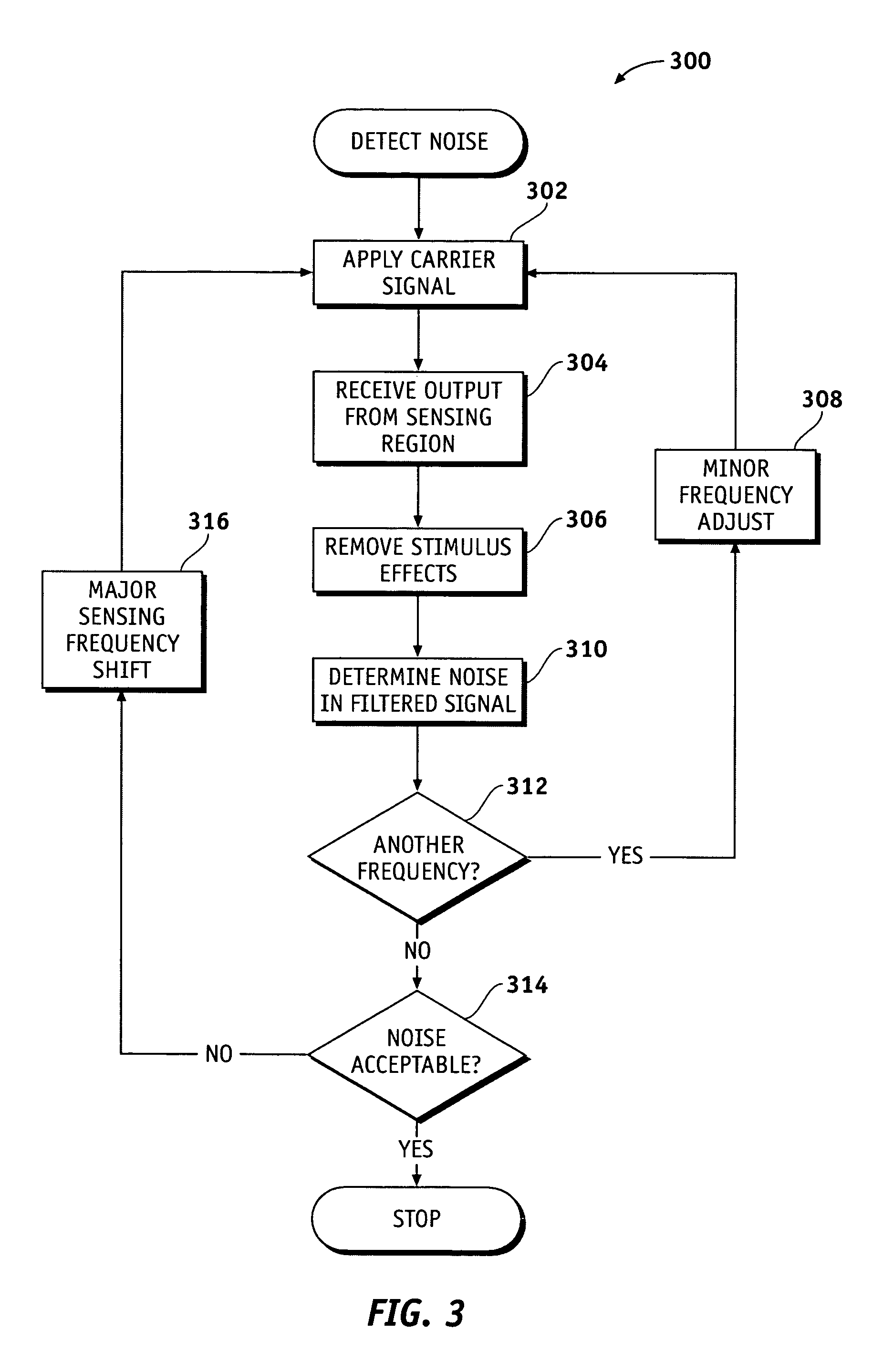
[0013]According to various exemplary embodiments, a carrier signal having one of two or more closely spaced sensing frequencies is applied to a carrier modulating sensor, demodulated, filtered, and analyzed for noise. The same procedure is then applied for the remaining closely-spaced frequencies. The sensing frequencies are chosen such that they are spaced within the bandwidth of the demodulation filter but greater than the expected bandwidth of the stimulus. Regardless of the frequency of the applied carrier signal, the frequency bandwidth of the demodulated stimulus is mostly invariant, but the frequency band of the demodulated noise ch...


PUM


Abstract

Methods, systems and devices are described for detecting noise in a touchpad or other sensor that produces an output in response to a stimulus that is applied at or near a sensing region. According to various embodiments, a carrier signal is applied to the sensing region at two or more frequencies to thereby produce an output from the sensing region at each frequency. Each of the outputs is demodulated and filtered by a demodulation filter having a demodulation filter bandwidth. The various frequencies applied to the carrier signal are selected such that a difference between the frequencies is less than the demodulation filter bandwidth. At least some of the effects of the stimulus are removed from the outputs produced by the various carrier frequencies to produce two or more filtered outputs. The filtered outputs are then added, combined or otherwise processed to detect noise contained therein. If noise contained in one or more of the filtered outputs reaches an unacceptable level, the carrier signal may be shifted to a new sensing frequency for subsequent operation of the sensor.

Description

TECHNICAL FIELD[0001]The present invention generally relates to position and proximity sensors such as touchpads, and more particularly relates to devices, systems and methods capable of detecting or avoiding noise present in such sensors.BACKGROUND[0002]Position sensors are commonly used as input devices for computers, personal digital assistants (PDAs), media players, video game players, consumer electronics, cellular phones, payphones, point-of-sale terminals, automatic teller machines, kiosks and the like. One common type of sensor used in such applications is the touchpad-type sensor, which can be readily found, for example, as an input device on many notebook-type computers. A user generally operates the sensor by moving a finger, stylus or other stimulus near a sensing region of the sensor. The stimulus creates a capacitive, inductive or other electrical effect upon a carrier signal applied to the sensing region that can be detected and correlated to the position or proximity...

Claims


Application Information

Patent Timeline
Patent Type & Authority Patents(United States)
IPC IPC(8): G06F15/00H04B1/00
CPCG06F3/044G06F3/0418
Inventor HARGREAVES, KIRK
Owner SYNAPTICS INC
Why Eureka
Try Eureka