Adjustable snap buckle

a technology of snap buckles and straps, which is applied in the direction of snap fasteners, fastening devices, buckles, etc., can solve the problems of difficult strap length adjustment and the inability of buckles to connect separate segments of cords together, and achieve the effect of strap length and easy adjustmen

Inactive Publication Date: 2006-04-25
OLSON CASEY
View PDF14 Cites 29 Cited by
  • Summary
  • Abstract
  • Description
  • Claims
  • Application Information

AI Technical Summary

Benefits of technology

[0006]Objects of the present adjustable strap buckle are to detachably connect a segment of a strap to another...

Problems solved by technology

The tightness of the bind prevents the strap from sliding, but makes adjusting the length of the strap difficult.
The push button on th...

Method used


Image

  • Adjustable snap buckle
  • Adjustable snap buckle
  • Adjustable snap buckle

Examples


second embodiment

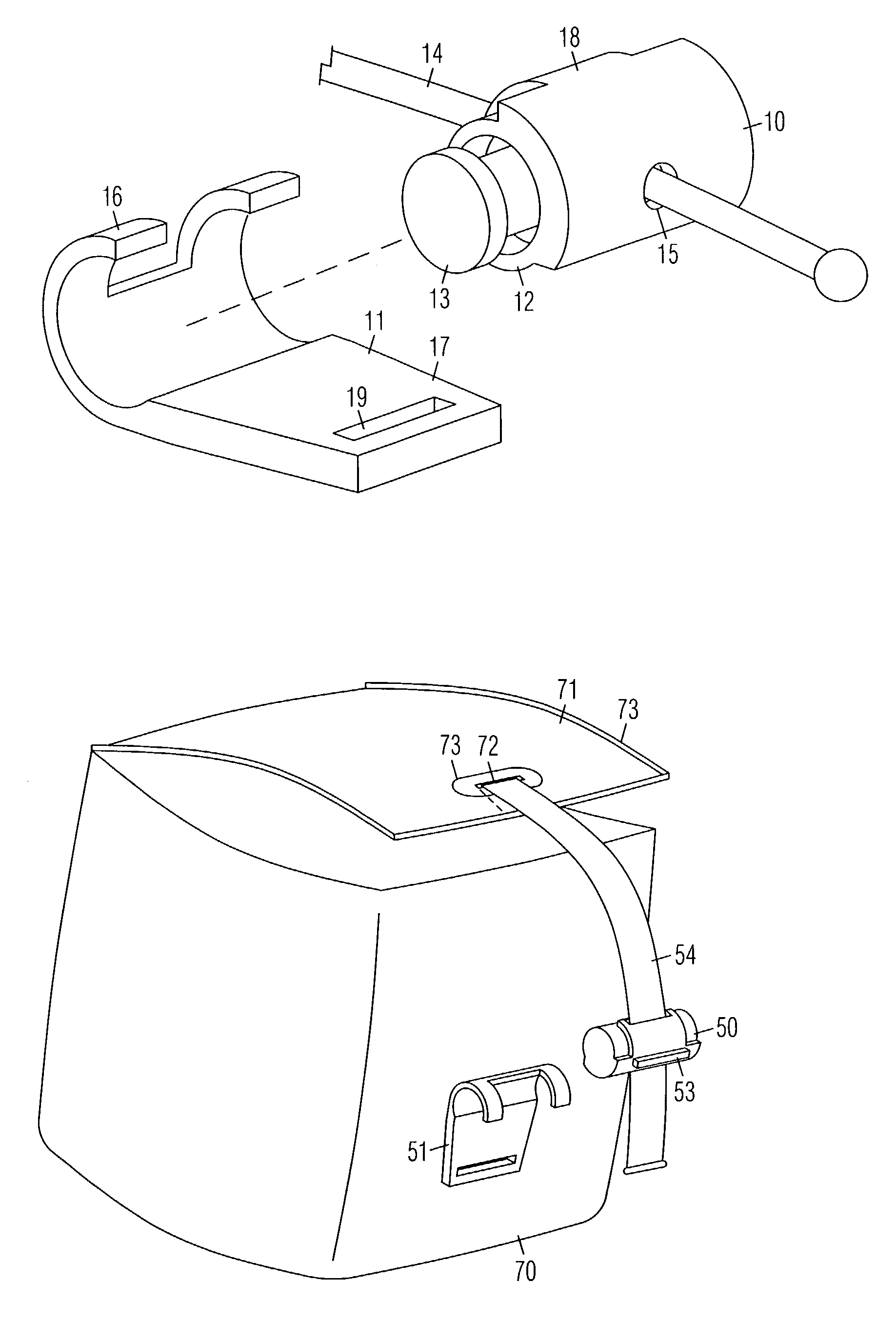
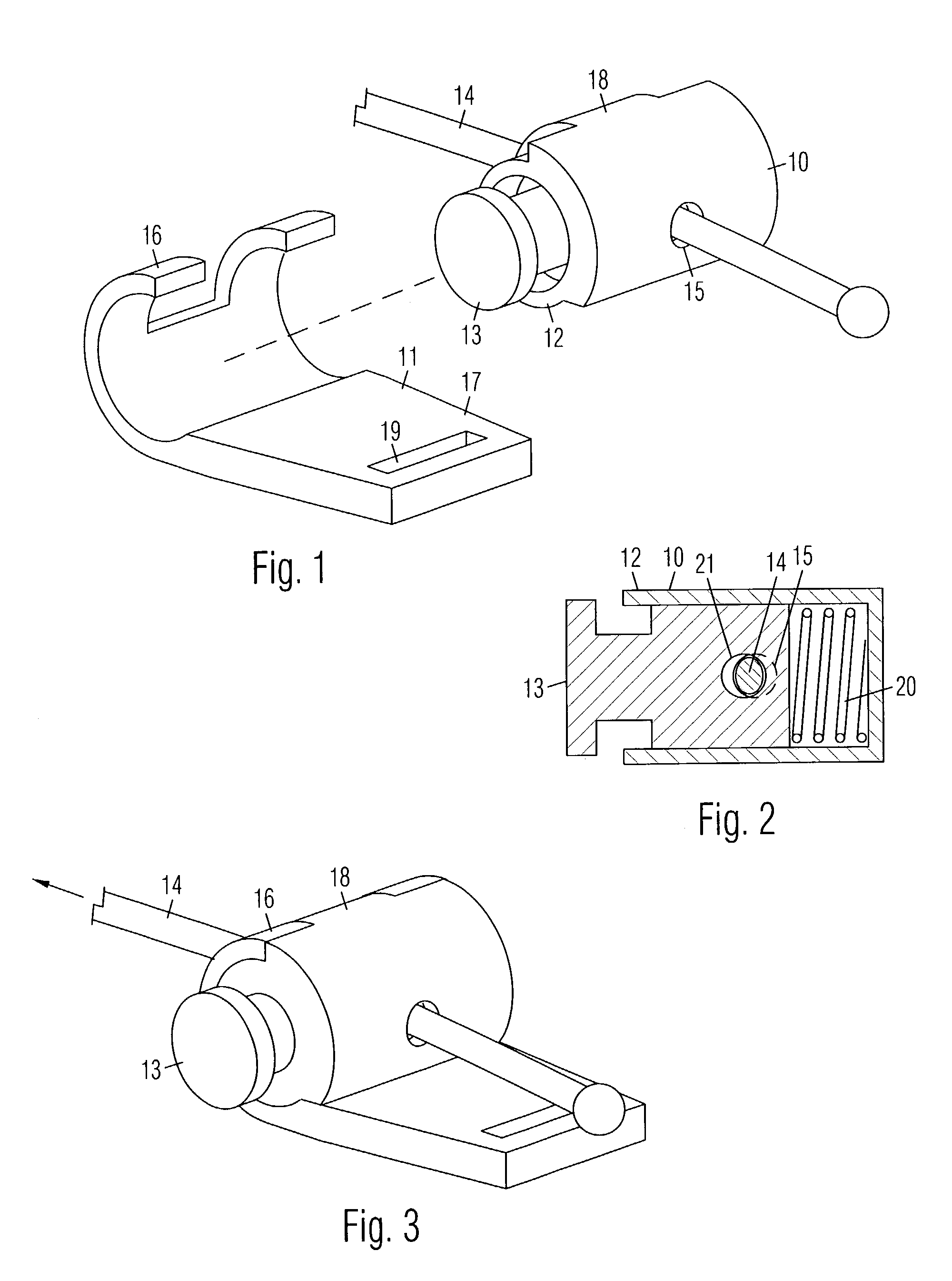
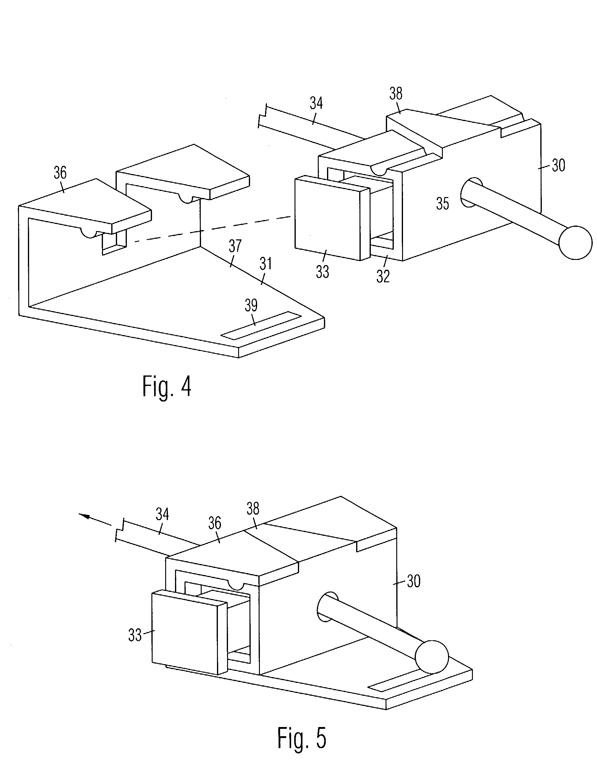
[0022]the adjustable strap buckle shown in FIGS. 4–5 is comprised of a barrel member 30 for detachably positioning in a hook member 31. Barrel member 30 is comprised of a tubular housing 32 with a push button 33 projecting from an open end. In this example, barrel member is rectangular in cross section. A strap 34 is positioned through housing holes 35 (one shown) on opposite sides of housing 32. In this example, strap 34 is comprised of a round cord.

[0023]Hook member 31 is comprised of side-by-side hooks 36 attached to an anchor member 37. In this example, hooks 36 are comprised of angular brackets. A key 38 on the outer surface of housing 32 aligns barrel member 30 inside hooks 36 to prevent sliding. Key 38 is comprised of a plate with converging sides for facilitating sliding between hooks 36. A hole 39 in anchor member 37 enables attachment to another end of strap, another strap, clothing, a bag, luggage, etc. Hole may be of any shape. Button 33 includes a button hole (not shown...

third embodiment

[0024]the adjustable strap buckle shown in FIGS. 6–8 is comprised of a barrel member 50 for detachably positioning in a hook member 51. Barrel member 50 is comprised of a tubular housing 52 with a push button 53 projecting from a longitudinal side. In this example, barrel member 50 is cylindrical, but it may be rectangular. A strap 54 is positioned through housing slots 55 (one shown) on opposite sides of housing 52. In this example, strap 54 comprised of flat webbing. Hook member 51 is comprised of side-by-side hooks 56 attached to an anchor member 57. In this example, hooks 56 are curved. A key 58 on outer surface of housing 52 aligns barrel member 50 inside hooks 56 to prevent sliding or rotation. Key 58 is preferably T-shaped as shown, wherein the vertical segment of the “T” is for being positioned between hooks 56, and the transverse segment is for being positioned against the ends of hooks 56. A hole 59 in anchor member 57 enables attachment to another end of strap, another st...


PUM


Abstract

An adjustable strap buckle is comprised of a barrel member detachably positioned in a hook member. The barrel member is comprised of a tubular housing with a spring loaded push button projecting from an open end. A button hole is positioned through the button, and housing holes are positioned through opposite walls in the housing. A strap is positioned through all the holes. When the button is released, the button hole is misaligned with the housing holes to bind the strap. When the button is pressed, the holes are all aligned for releasing the strap for sliding. The hook member is comprised of spaced apart hooks attached to an anchor member for attaching to clothing, a bag, luggage, etc. The barrel member is transversely positioned inside the hooks to secure the strap, wherein the segment of the strap extending from the barrel member is also positioned between the hooks.

Description

BACKGROUND OF THE INVENTION[0001]1. Field of the Invention[0002]The invention broadly relates to strap buckles.[0003]2. Prior Art[0004]A typical buckle for a flat strap is comprised of a male member and a female member attached to separate segments of a strap. The male and female members are arranged to be connected together for connecting the strap. The male member includes prongs for mating with a slot in the female member. One or both members may include a slide buckle for adjusting the length of the strap segment, which is bound inside the slide buckle by being positioned along a tightly curved path through the buckle. The tightness of the bind prevents the strap from sliding, but makes adjusting the length of the strap difficult.[0005]A typical buckle for a round cord is comprised of a hollow cylinder with a button movably positioned inside. The button is biased outwardly by an internal spring. A hole in the button is misaligned with holes in the cylinder when the button is rel...

Claims


Application Information

Patent Timeline
IPC IPC(8): A44B11/10
CPCA44B11/10A44B11/28A45C13/1053A45C13/1076Y10T24/3969Y10T24/3984Y10T24/4049Y10T24/4019
Inventor OLSON, CASEY
Owner OLSON CASEY
Why Eureka
Try Eureka