Integrated dual circuit evaporator

a dual-circuit evaporator and integrated technology, applied in indirect heat exchangers, refrigeration components, lighting and heating apparatuses, etc., can solve the problems of reducing the efficiency of the evaporator, the actual refrigeration cycle may deviate from the ideal cycle, and the blower motor power for this portion of the air supply is virtually wasted, so as to improve the latent capacity percentage of the total heat removal, the effect of enhancing the latent heat removal and reducing the amount of humidity

Inactive Publication Date: 2006-04-25
OLIVE TREE PATENTS 1
View PDF6 Cites 29 Cited by
  • Summary
  • Abstract
  • Description
  • Claims
  • Application Information

AI Technical Summary

Benefits of technology

[0020]Another objective of the present invention is to provide a method for enhancing latent heat removal in a thermal transfer cycle by cooling the air to temperatures even lower than standard evaporators so that the air is substantially below the dew point temperature of the air. By increasing the temperature difference below the dew point temperature, more humidity is removed and the latent capacity percentage of the total heat removal is increased.
[0021]Yet another objective of the present invention is to provide a method for increasing the superheat capacity of a refrigerant in a thermal transfer cycle. This increases the total change in enthalpy of the refrigerant per unit mass flow and thereby increases overall capacity. This is accomplished by putting the warmer superheat region of the evaporator upstream in the air supply from the colder region(s) thereby supplying more heat to this superheat region.
[0022]Even yet another objective of the present invention is to provide an apparatus and method that will increase overall refrigerant mass flow thereby increasing refrigerant capacity while doing so in a more efficient manner.
[0023]And yet another objective of the present invention is to provide a method and apparatus that will improve the load performance of a two circuit evaporator when one circuit is inactive, whereby capacity, dehumidification, and mass flow are all greatly improved.

Problems solved by technology

However, the actual refrigeration cycle may deviate from the ideal cycle primarily because of pressure drops associated with fluid flow and heat transfer to or from the surroundings.
When one circuit is inactive, the air passing through the inactive circuit acts like bypass air and no cooling to this fraction of the circulated air is accomplished and the blower motor power for this portion of the air supply is virtually wasted.

Method used


Image

  • Integrated dual circuit evaporator
  • Integrated dual circuit evaporator
  • Integrated dual circuit evaporator

Examples


Embodiment Construction

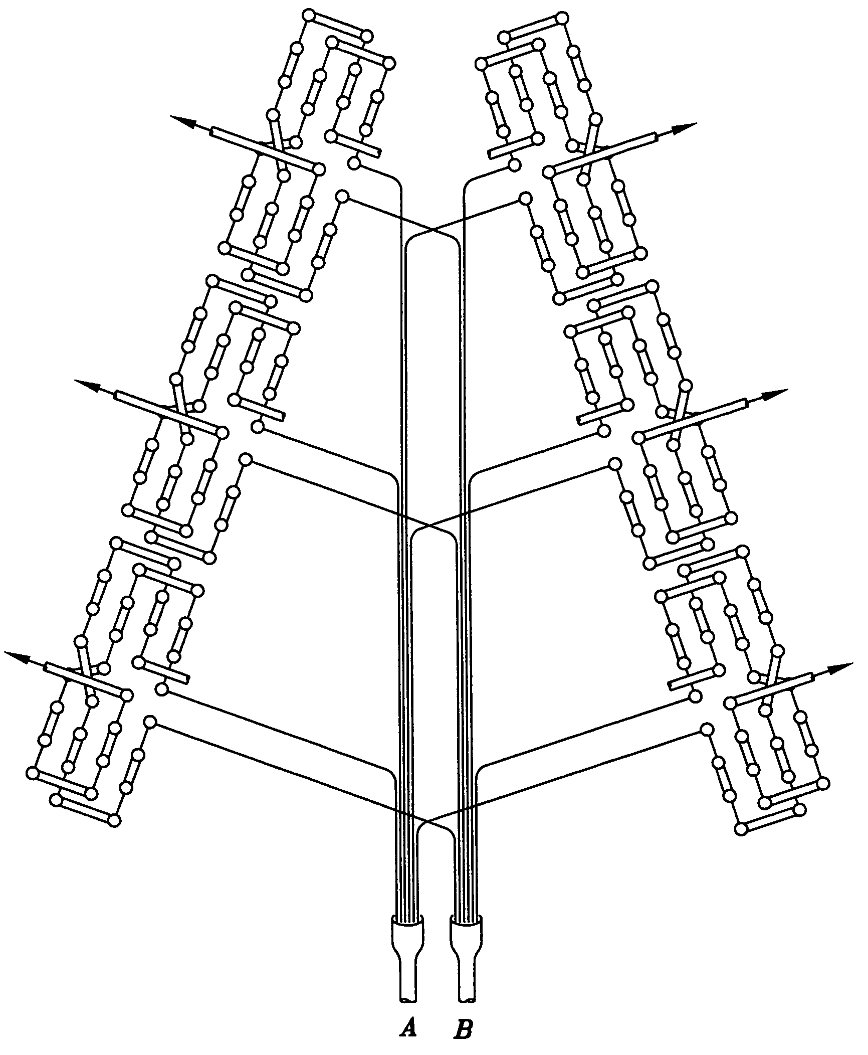
[0051]With reference to the drawings and in particular to FIGS. 3, 3a, 4a, 4b, 4c, 5, 6, 6a, 6b, 6c and 6d thereof, a new and improved dual circuit evaporator system embodying the principles and concepts of the present invention and generally designated by the reference number 10 will be described. The dual circuit evaporator system of the present invention comprises circuiting one circuit of a dual circuit evaporator in such away as to prevent the possibility of bypass air when one circuit is inactive, wherein the circuit is designed to flow in each circuit on a diagonal to the direction of air flow or for the first one-half of the first circuit to be in front of the second one-half of the second circuit and the first one-half of the second circuit to be in front of the second one-half of the first circuit. Further, the dual circuit evaporator system incorporates the principle of temperature counter flow design and comprises circuiting each circuit of the dual circuit evaporator in...


PUM


Abstract

An evaporator system comprised of two individual refrigerant circuits, integrated in such a way that if one circuit is not in operation, no portion of the airflow through the evaporator fails to come into contact with the refrigerant in the active circuit. This eliminates the possibility of so-called bypass air (air passing through inactive region of evaporator). An extreme example of bypass air is illustrated in the use of a split face evaporator where on half of the evaporator is active and the other half is inactive. The purpose of such an integrated dual circuit evaporator being to improve part load performance of a refrigerating or air conditioning system when one circuit of the system is inactive.

Description

CROSS-REFERENCE TO RELATED APPLICATIONS[0001]This invention claims priority of provisional application No. 60 / 405,771, filed Aug. 23, 2002, the disclosure of which is incorporated by reference herein.BACKGROUND OF THE INVENTION[0002]1. Field of the Invention[0003]This invention relates to a two circuit evaporator system of increased refrigeration capacity and increased dehumidification capacity, especially when one circuit is inactive, for use with any two circuit air conditioner, refrigeration or heat pump system. This invention more particularly pertains to an apparatus and method comprising a two circuit evaporator system that allows for integration of the two circuits in such a way as to eliminate any possibility of any portion of the air passing through the face of the evaporator, when one circuit is inactive, not coming into contact with some portion of the active circuit. Further, this invention incorporates the principles of increasingly colder refrigerant temperatures count...

Claims


Application Information

Patent Timeline
Patent Type & Authority Patents(United States)
IPC IPC(8): F25B39/02F28D1/04F28D1/047
CPCF25B39/02F28D1/0477F28D1/0443F28D1/0426
Inventor HEBERT, THOMAS H.
Owner OLIVE TREE PATENTS 1
Why Eureka
Try Eureka