System and method for cooling air

a cooling system and air technology, applied in the field of air conditioning systems, can solve the problems that the air conditioning unit cannot catch up and cool the space down to the desired temperature, and achieve the effect of reducing the amount of air in the air conditioning unit and reducing the amount of air in the air

Inactive Publication Date: 2005-04-07
JENSEN TIM ALLAN NYGAARD
View PDF33 Cites 31 Cited by
  • Summary
  • Abstract
  • Description
  • Claims
  • Application Information

AI Technical Summary

Problems solved by technology

If a system goes above the maximum temperature for which the unit was sized, the air co

Method used


Image

  • System and method for cooling air
  • System and method for cooling air
  • System and method for cooling air

Examples


Embodiment Construction

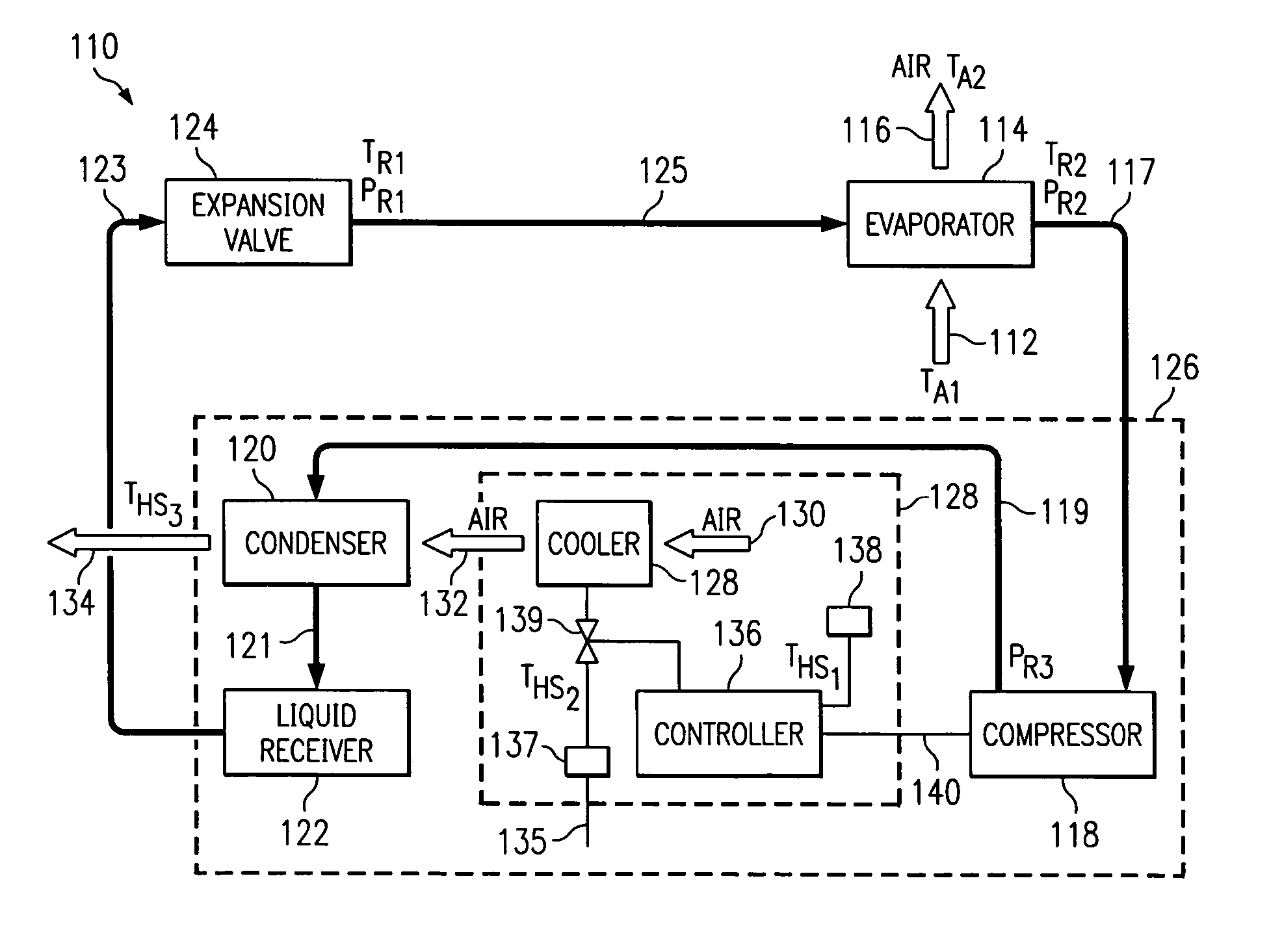
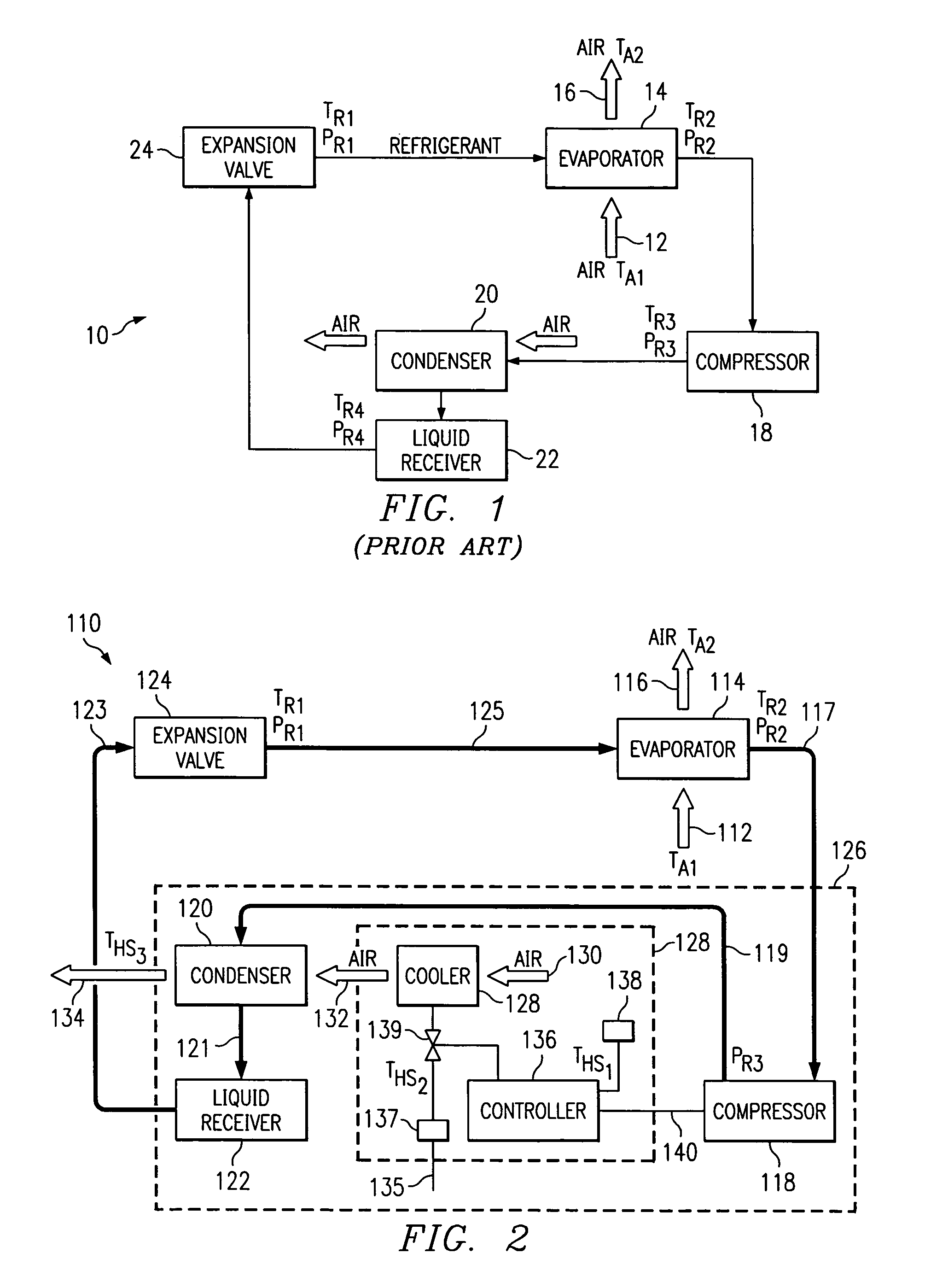
[0023] The preferred embodiment of the present invention and its advantages are best understood by referring to FIGS. 2-7 of the drawings, like numerals being used for like and corresponding parts of the various drawings.

[0024] Referring to FIG. 2, there is shown a system 110 for cooling a conditioned space or air represented by arrow 112. Air 112, which is at a temperature TA1, passes across an evaporator 114 that removes heat from air 112 to produce cooled or conditioned air represented by arrow 116, which is at a temperature TA2. The heat removed in evaporator 114 is delivered to a refrigerant within the evaporator 114. The refrigerant is at a temperature TR1 and a pressure PR1 before entering the evaporator 114. The heat rejected from air 112 to the refrigerant in the evaporator 114 vaporizes the refrigerant and may raise the temperature to TR2. The refrigerant is delivered from evaporator 114 to compressor 118 by conduit 117.

[0025] The compressor 118 increases the pressure of...


PUM


Abstract

A system and method for cooling air includes using a refrigerant cooling system and further using a refrigerant liquefaction subsystem or method that includes using a heat sink cooler (“pre-cooler”) to cool the heat sink coolant before it is used to cool the refrigerant in the condenser. One aspect of the refrigerant liquefaction subsystem may use a water mist, which may be prepared by atomizers, high pressure nozzles, piezo-electric ultrasonic nebulizers, or the like, to cool the heat sink coolant.

Description

RELATED PATENT APPLICATION [0001] This application is a continuation of U.S. patent application Ser. No. 10 / 360,136, filed Feb. 7, 2003, now U.S. Pat. No. 6,823,684, which claims the benefit of U.S. Provisional Application No. 60 / 354,979, filed Feb. 8, 2002, entitled, “System and Method for Cooling Air,” which is hereby incorporated by reference in its entirety.TECHNICAL FIELD OF THE INVENTION [0002] The present invention relates to air conditioning systems and more particularly to a system and method for cooling air that includes an air pre-cooler and may further include an additional cooler of refrigerant. BACKGROUND OF THE INVENTION [0003] Refrigeration systems or evaporative systems for cooling are well-known in the art. Refrigeration is the process of removing heat from a substance or space in order to lower its temperature. To extract heat energy from the air, the air is placed in contact with a material at a lower temperature so that heat flow will occur in a descending tempe...

Claims


Application Information

Patent Timeline
IPC IPC(8): F24F5/00F24F13/22F25B49/02F28D5/00
CPCF24F5/0035F24F6/14F24F2013/225Y02B30/545F25B2339/041F28D5/00F25B49/027Y02B30/54
Inventor JENSEN, TIM ALLAN NYGAARD
Owner JENSEN TIM ALLAN NYGAARD
Why Eureka
Try Eureka