Barrier shield for a bus

a barrier shield and bus technology, applied in the direction of door/window protective devices, pedestrian/occupant safety arrangements, transportation items, etc., can solve the problems of special problems of the driver, inability to defend himself/herself, and difficulty for the driver to monitor the passenger area, so as to maintain the integrity of the security surround and reduce or eliminate optical glare and reflection

a barrier shield and bus technology, applied in the direction of door/window protective devices, pedestrian/occupant safety arrangements, transportation items, etc., can solve the problems of special problems of the driver, inability to defend himself/herself, and difficulty for the driver to monitor the passenger area, so as to maintain the integrity of the security surround and reduce or eliminate optical glare and reflection

US7032946B1Inactive Publication Date: 2006-04-25BUS SOLUTIONS COMPANY

Image

  • Barrier shield for a bus
  • Barrier shield for a bus
  • Barrier shield for a bus

Examples


Embodiment Construction

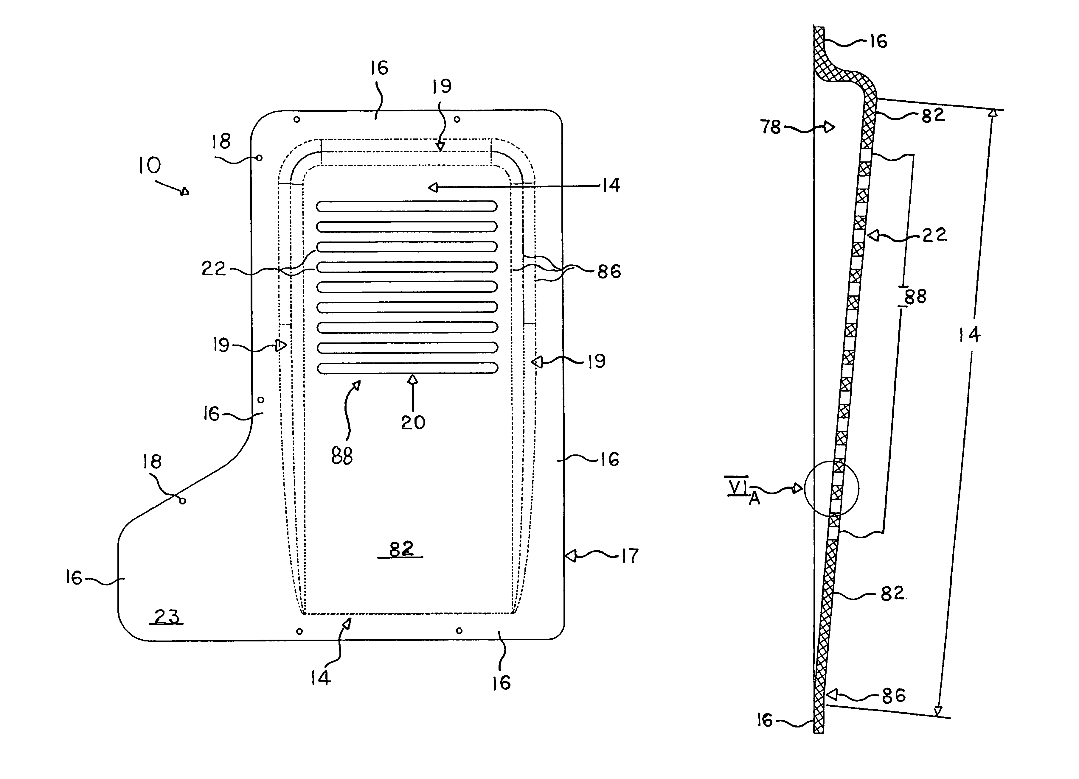
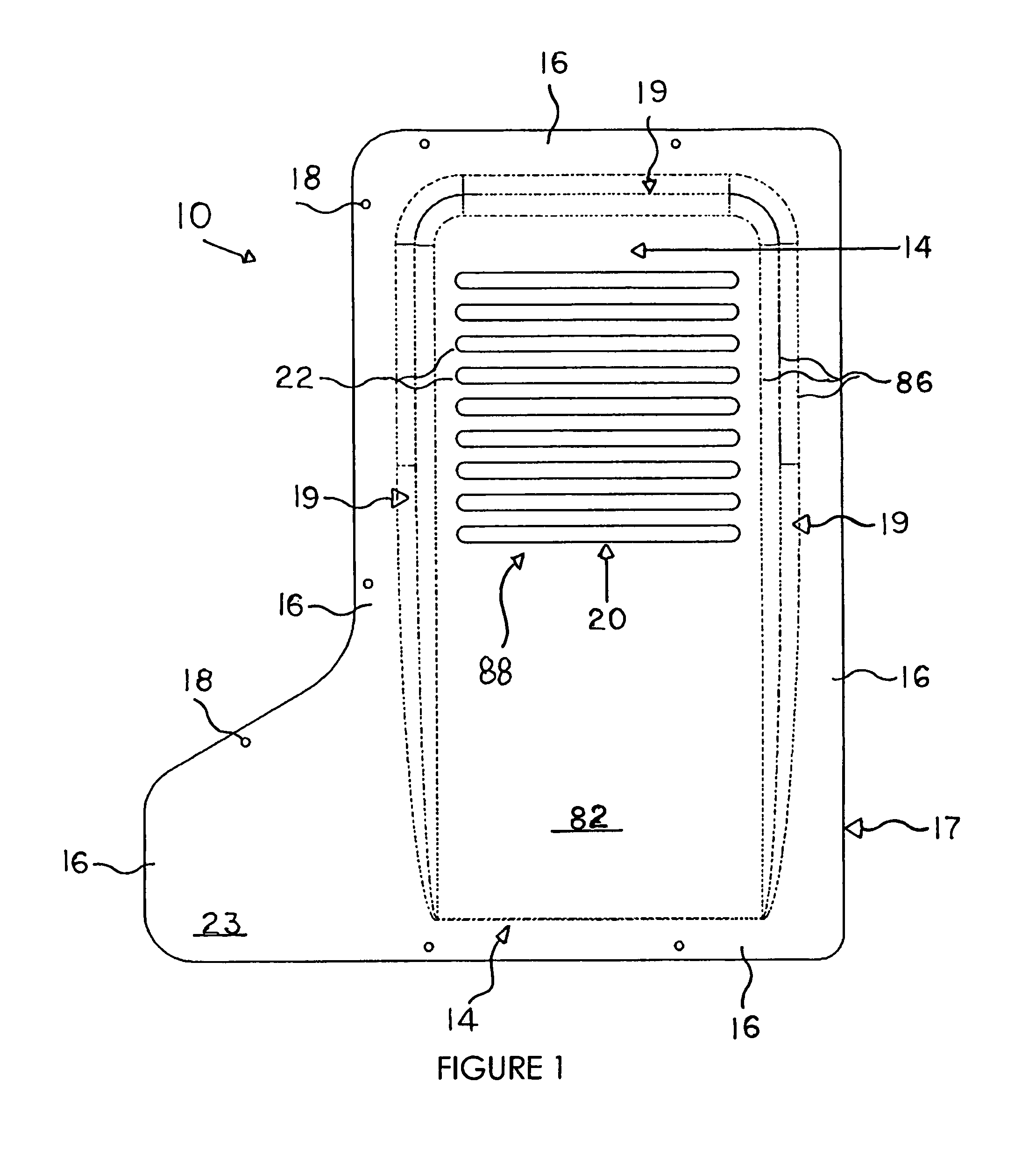
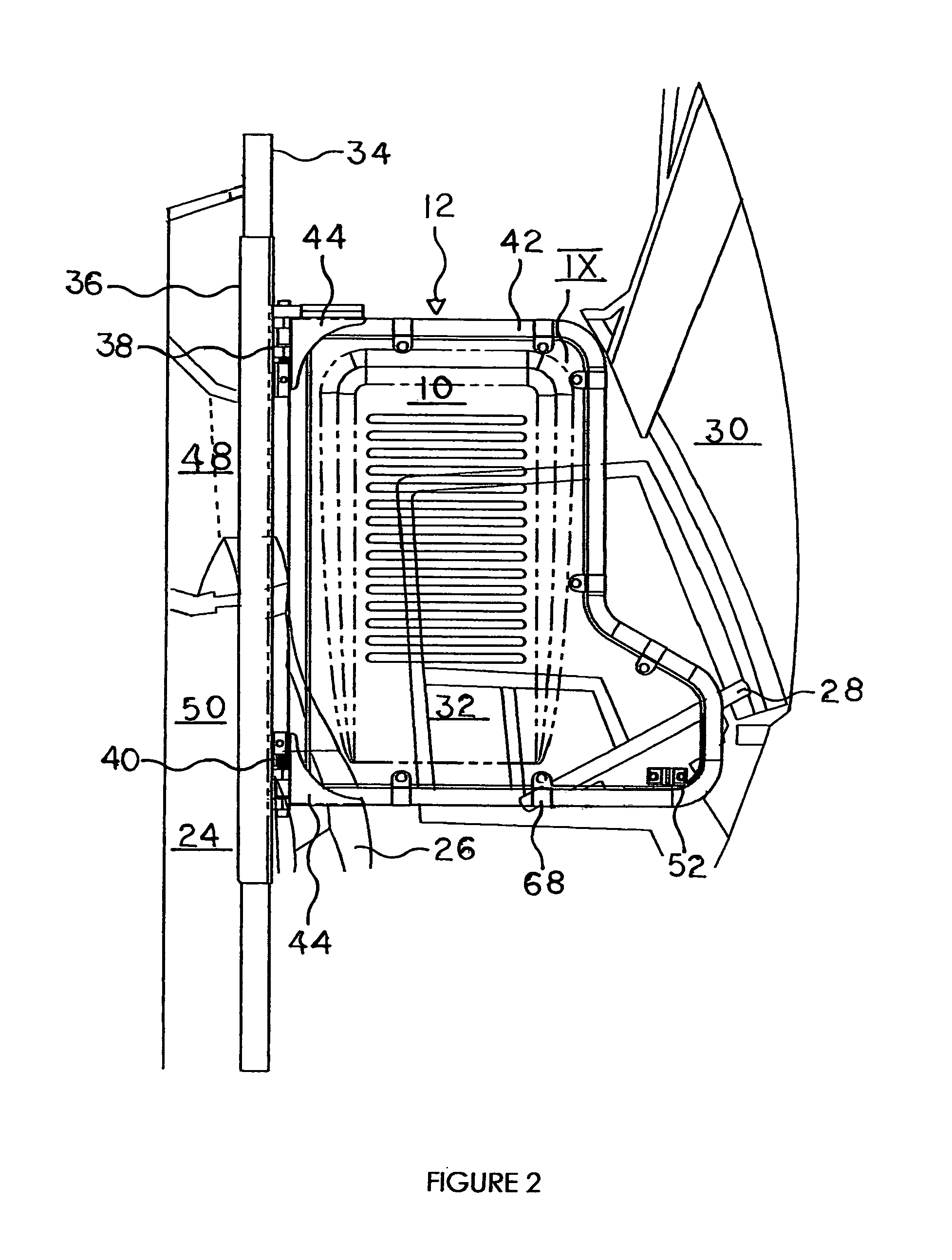
[0032]Referring to FIG. 1, a barrier shield 10 is shown by a front elevational view removed from a closure door 12 of FIG. 2. As seen in FIG. 1, the preferred embodiment of the present invention is an integrally formed transparent plastic barrier shield 10. The barrier shield 10 comprises a slanted high visibility insert 14 with an apertured area 88 having at least one or more openings therein with predetermined shapes such as a grate area with a plurality of horizontal slots therein such as shown in the FIG. 3, for example. Attachment means 18 such as bolt holes are positioned about mounting flanges 16 to be discussed below. A latch mounting area 23 being an extended panel section is positioned on the bottom of the barrier shield 10. The slanted high visibility insert 14 has a plurality of predetermined openings 20 as seen in FIG. 1, approximately 8 to 15 horizontal viewing ports or slots 22 which span the width of the slanted high visibility insert 14. As seen in FIG. 1, the dashe...


PUM


Abstract

The present invention is a barrier shield having selective transparent areas therein that incorporates particular optical glare and reflection reduction methods utilizing diffractive and grating techniques within a tilted planar surface having selective openings therethrough. This barrier shield is mounted within the closure door for correcting the transmissive optical imagery enabling the driver / operator to view the passengers through the closure door barrier shield using, typically, the inside rear-view mirror without compromise to safety or security.

Description

CROSS-REFERENCE TO RELATED APPLICATIONS[0001]This patent application incorporates by reference provisional patent application 60 / 525,789, filed Nov. 29, 2003, titled “Anti Glare Passenger Bus Barrier Shield” and this is the regular utility patent application of this provisional patent application.BACKGROUND OF THE INVENTION[0002]1. Field of the Invention[0003]The present invention relates to passenger buses and the like, and, in particular, relates to devices to prevent passengers from interfering with the driver, and, in greater particularity, relates to doors that act as a barrier shield to the passenger area of the bus, as drivers now face heightened security issues.[0004]2. Description of the Prior Art[0005]Intercity passenger buses may be used to transport passengers from point to point such as Greyhound buses. Similar buses may also be used in mass transit operations within a metropolitan area. In any event, the bus driver is normally preoccupied with driving the bus and thus ...

Claims


Application Information

Patent Timeline
25 Apr 2006
Publication
US7032946B1
IPC
B60N3/00; E06B3/68
CPC
B60R21/12; B60R2021/0067
Inventors
BROWN, THOMAS C.