Rack enclosure

Active Publication Date: 2006-04-25
AMERICA POWER CONVERSION CORP
View PDF8 Cites 185 Cited by
  • Summary
  • Abstract
  • Description
  • Claims
  • Application Information

AI Technical Summary

Benefits of technology

[0016]Various aspects of the invention may provide one or more of the following advantages. A single type of equipment enclosure can be used to contain electronic equipment regardless of an airflow pattern, e.g., front-to-back airflow or side-to-side airflow, used by the equipment to meet its cooling and ventilating needs. The enclosure can thereby help to simplify the planning, design and maintenance of a data center or network room. Equipment components using side-to-side airflow can be mounted in a rack housed within an enclosure having one or more doors, e.g., as an alternative to an open-frame rack, to provide enhanced security and protection of the equipment.
[0017]An enclosure, and/or a rack housed within the enclosure, configured to permit front-to-back airflow can be converted, e.g., easily and rapidly reconfigured, to accommodate the operating requirements of equipment using side-to-side airflow for cooling and ventilating. The enclosure interior can be configured to define an air intake chamber or plenum along a side, e.g., left side, of the rack that is substantially enclosed and can receive and contain cooling air from which equipment using side-to-side airflow may draw from to meet its cooling and ventilating requirements. The enclosure, and/or the rack housed within the enclosure, can be configured to permit one or more air ducts having multiple fans to be mounted in the rack adjacent to and between equipment components using side-by-side airflow to increase a volume of cooling air directed to air intakes along the components. Air ducts can be configured and disposed within the rack such that the multiple fans draw cooling air into the air ducts and the air ducts direct cooling air into the chamber or plenum. The enclosure and/or the rack can thereby be configured to pressurize the chamber or plenum by increasing volumes and/or flow rate of cooling air into the chamber or plenum. Increased volumes of cooling air can be provided to equipment using side-to-side airflow for cooling when the equipment is housed in an enclosure and/or mounted to a rack that is configured to provide front-to-back airflow. Performance reliability and useful life of electronic equipment using side-to-side airflow can be increased and overheating and equipment shutdown reduced when housed in a standard enclosure providing front-to-back airflow in comparison to other cooling solutions.
[0018]An enclosure, and/or a rack housed within the enclosure, configured to simultaneously accommodate the cooling and ventilating requirements of equipment using front-to-back airflow and equipment using side-to-side airflow can allow the rack to operate at a high power density. The enclosure and the rack can house a mix of different types of equipment using front-to-back airflow or side-to-side airflow within a single enclosure means, and can thereby eliminate the need for two separate enclosures and racks, each configured to meet one type of airflow required for cooling and ventilating. The single enclosure means, therefore, can reduce floor space required to house different types of equipment. An enclosure, and/or a rack housed within the enclosure, configured to simultaneously accommodate the cooling and ventilating requirements of equipment using front-to-back airflow and equipment using side-to-side airflow can accept and accommodate cooling needs of equipment components, e.g., using side-to-side airflow, having different front-to-back depths as well as having air intake vents located at vario

Problems solved by technology

Advancements in information technology (IT) equipment present challenges in creating a more effective IT environment in data centers and networking facilities.
However, IT equipment racks and enclosures generally cannot provide adequate cooling and ventilation for equipment that typically uses a side-to-side airflow, such as certain types of telecommunications equipment.
As a result, the air intakes of equipment using side-to-side airflow often do not receive sufficient cooling air required for proper operation of the equipment.
Insufficient cooling air can cause overtemperature shutdown and unreliable performance and reduced lifetime of the equipment.
IT equipment enclosures and racks configured to provide front-to-back airflow, therefore, are essentially incompatible with airflow patterns of some types of electronic equipment using side-to-side airflow for cooling and ventilating, such as certain types of telecommunications components.
Open-frame configurations do not confine hot and warm exhaust air within an enclosure or around equipment air intakes; however, such configurations do not prevent circulation of exhaust air to equipment air intakes and, therefore, do not overcome problems of insufficient cooling and overheating of equipment.
Telecommunications equipment disposed in side-by-side rack configurations are

Method used


Image

  • Rack enclosure
  • Rack enclosure
  • Rack enclosure

Examples


Embodiment Construction

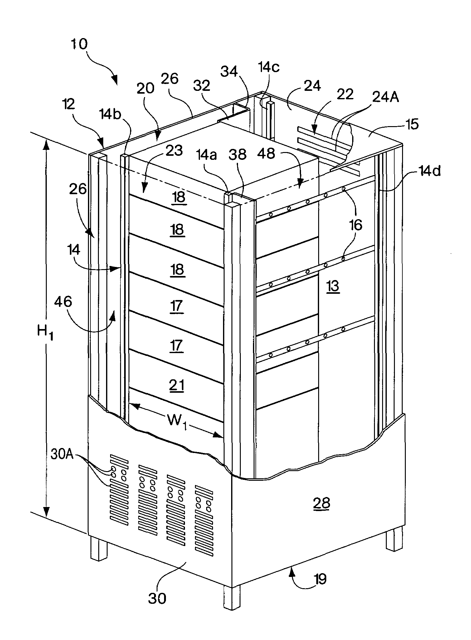
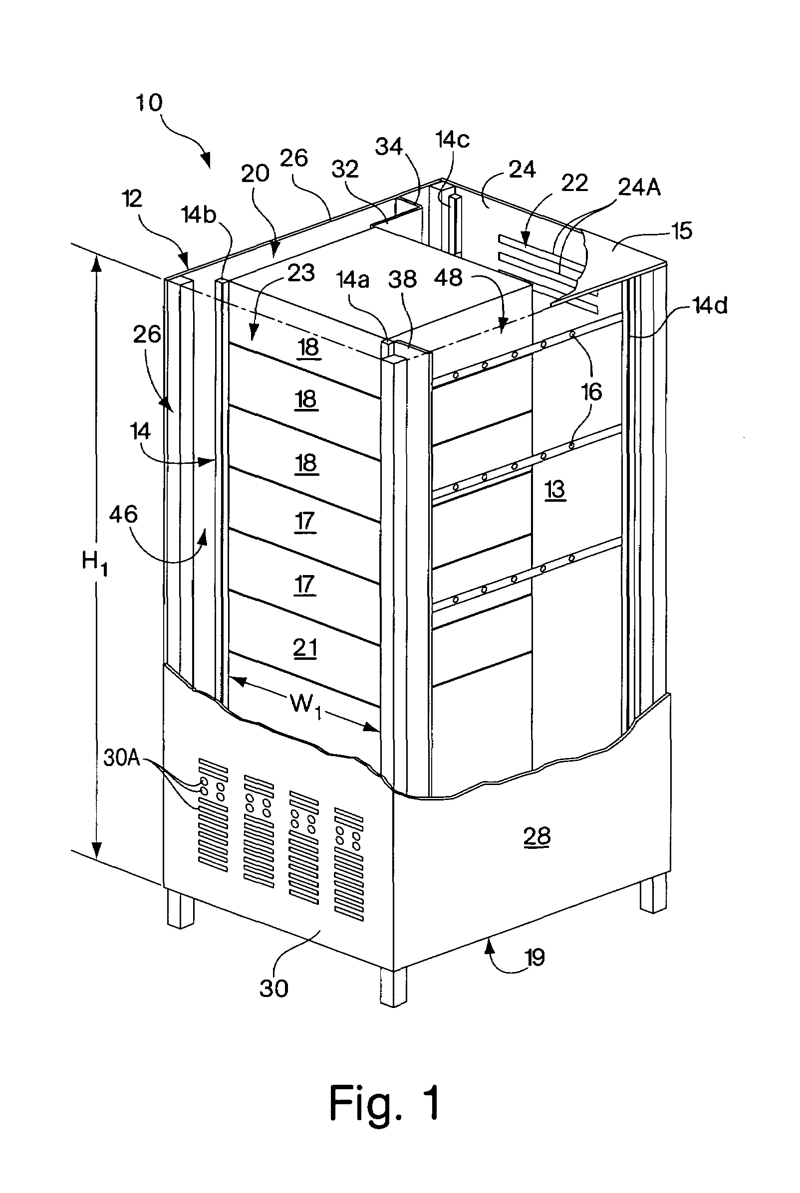
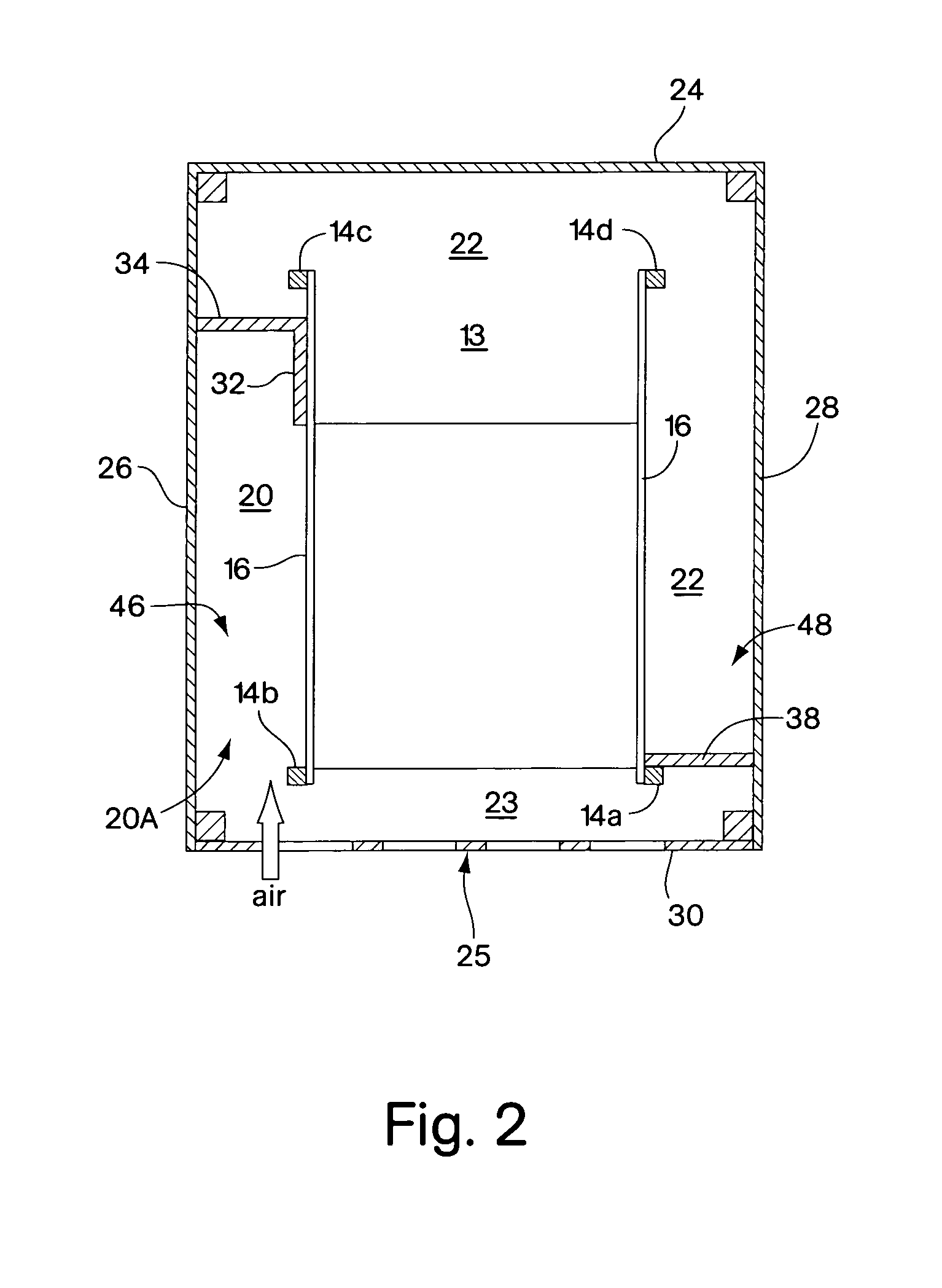
[0047]Aspects of the invention include an equipment rack enclosure having an interior configured for facilitating defined airflow conditions within the enclosure to meet cooling and ventilating requirements of rack-mounted equipment where the enclosure interior is structured and / or arranged to permit front-to-back airflow, e.g., used by information technology (IT) equipment, and side-to-side airflow, e.g., used by certain types of telecommunications equipment. An exemplary enclosure includes at least a first air intake plenum defined in the enclosure interior and disposed to contain cooling air that is directed and / or diverted from a front-to-back airflow to permit air to flow side-to-side through one or more sections of a rack. Different embodiments of an enclosure according to the invention permit an enclosure interior to be configured or adapted to accommodate different dimensions, e.g., depths, of different types of electronic equipment, while permitting airflow to meet the cool...


PUM


Abstract

An enclosure is provided for housing electronic equipment that accommodates the different cooling and ventilating requirements of different types of equipment. The enclosure is constructed and arranged to support cooling airflow in a front-to-back configuration through the enclosure and in a side-to-side configuration from one side to an opposite side of the enclosure. The enclosure can thereby provide within a single enclosure means cooling air for components using front-to-back airflow for cooling, such as information technology (IT) equipment, and for components using side-to-side airflow, such as certain types of telecommunications equipment. The enclosure can thereby support a mix of IT and telecommunications equipment, providing flexibility and adaptability in network room and data center configuration. The enclosure is further configured to separate intake air used by equipment for cooling from exhaust air vented by equipment into its interior during operation. As a result, the enclosure promotes sufficient equipment cooling and prevents/minimizes equipment overheating.

Description

FIELD OF THE INVENTION[0001]The invention relates to an enclosure for use with rack-mounted equipment.BACKGROUND OF INVENTION[0002]Advancements in information technology (IT) equipment present challenges in creating a more effective IT environment in data centers and networking facilities. Equipment enclosures designed for high power density applications employing servers and networking equipment typically must provide not only effective cable management and power distribution, but also adequate cooling and ventilation to assure proper and reliable operation of equipment. Equipment rack enclosures for use in such high heat generating applications are primarily configured and equipped to provide front-to-back airflow to accommodate the standard front-to-back airflow pattern used by IT equipment for cooling and ventilation. However, IT equipment racks and enclosures generally cannot provide adequate cooling and ventilation for equipment that typically uses a side-to-side airflow, such...

Claims


Application Information

Patent Timeline
IPC IPC(8): H05K7/20
CPCH05K7/20572
Inventor RASMUSSEN, NEIL
Owner AMERICA POWER CONVERSION CORP
Why Eureka
Try Eureka