Systems and methods for wavefront measurement

a technology of wavefront measurement and system, applied in the direction of optical apparatus testing, optical radiation measurement, instruments, etc., can solve problems such as system manufacturing flaws

Inactive Publication Date: 2006-04-25
ENTERPRISE PARTNERS VI +1
View PDF66 Cites 53 Cited by
  • Summary
  • Abstract
  • Description
  • Claims
  • Application Information

AI Technical Summary

Problems solved by technology

As non-limiting examples, measuring deviations, also referred to as “aberrations”, in a wavefront produced by an optical system, such as a telescope, can r

Method used


Image

  • Systems and methods for wavefront measurement
  • Systems and methods for wavefront measurement
  • Systems and methods for wavefront measurement

Examples


Embodiment Construction

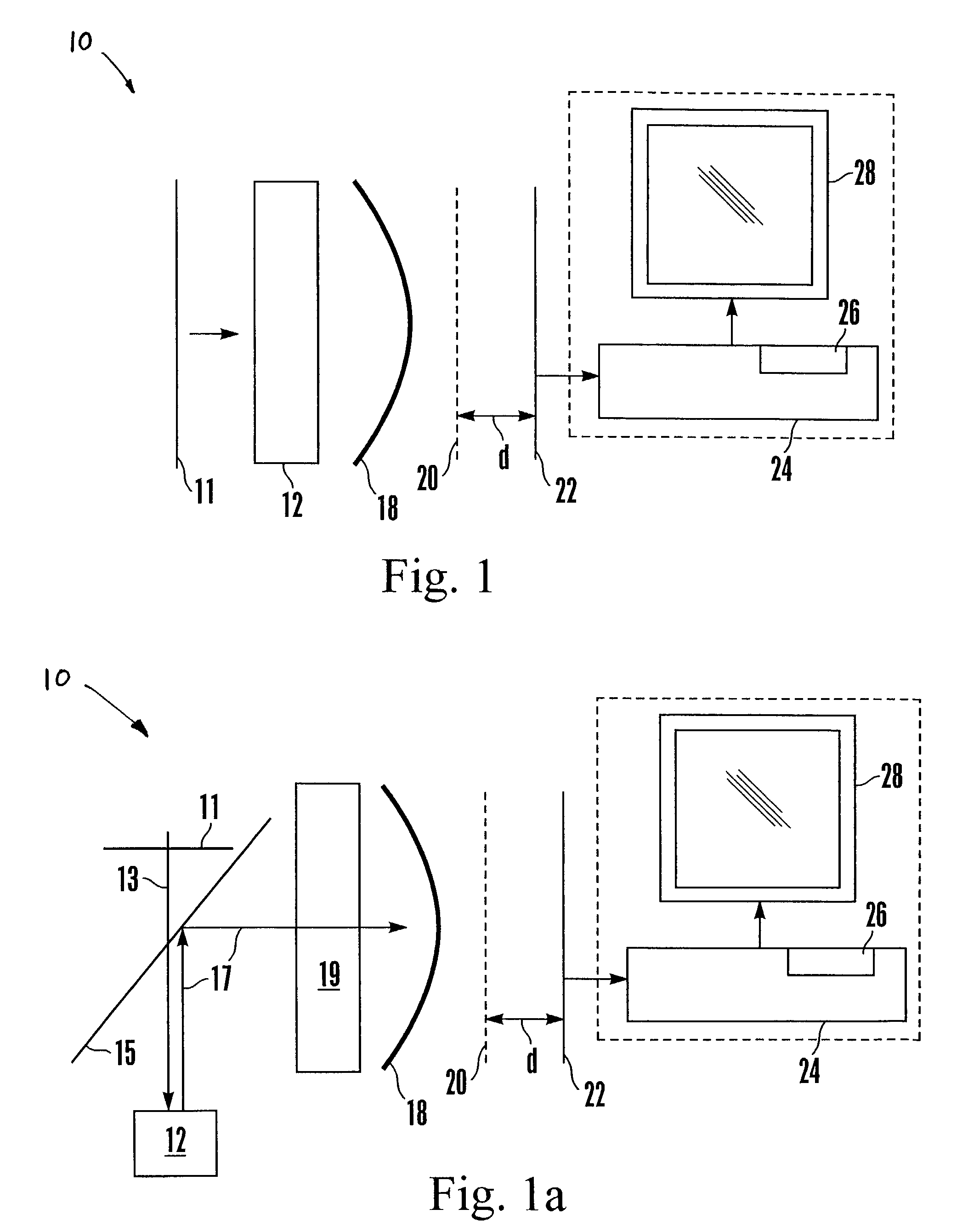
[0025]Referring initially to FIG. 1, a wavefront sensor is shown, generally designated 10. As illustrated in FIG. 1, a reference wavefront 11 can pass through (or, be reflected from) a system or element 12 (optical or otherwise). The system or element 12 can be an optics system, such as a telescope system, or it can be a human eye, or other object having properties, e.g., aberrations or curvature, sought to be measured.

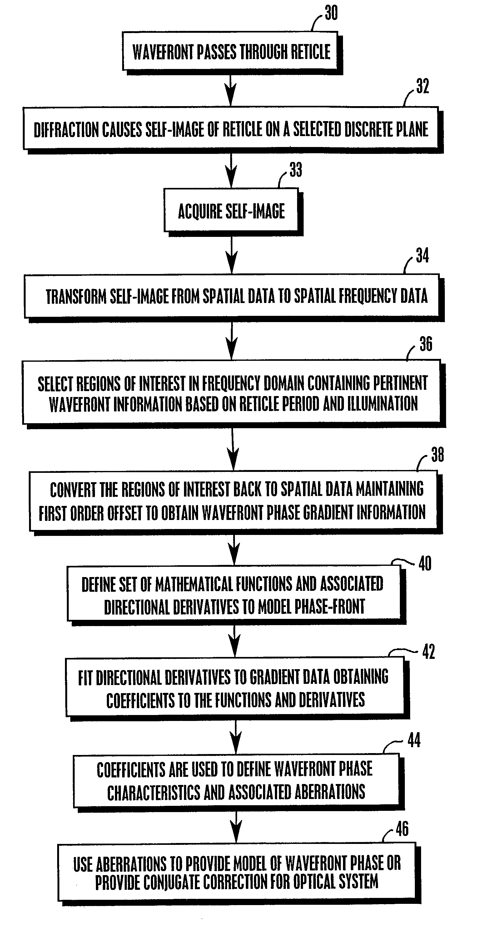
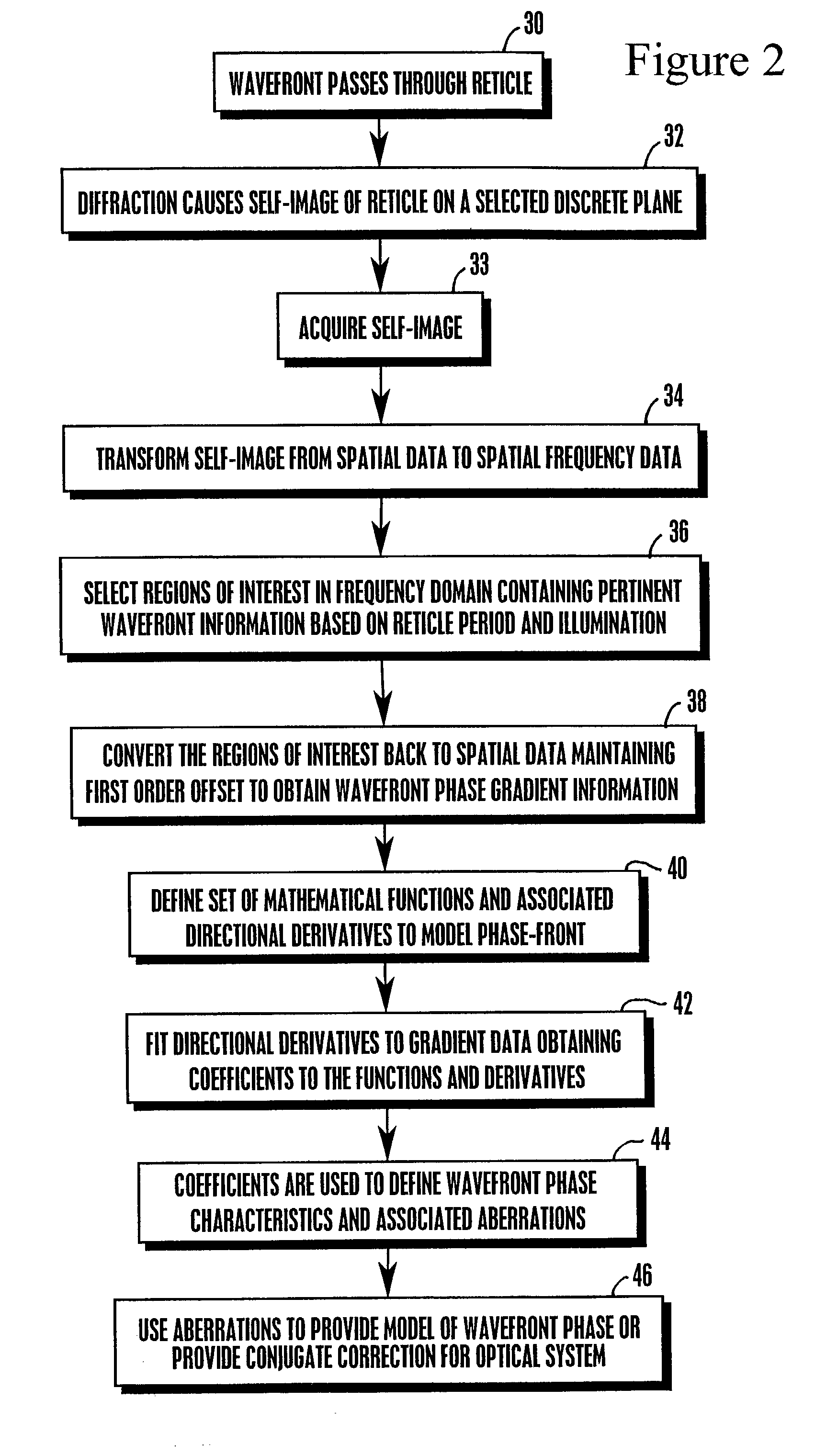
[0026]As shown in FIG. 1, a transferred wavefront 18, i.e., the wavefront 11 after having passed through or having been reflected from the system or element 12, passes through a reticle 20. For example, this reticle 20 may comprise without limitation, a diffraction grating, Ronchi ruling, or grid pattern. The reticle 20 diffracts the wavefront 18, and the diffracted wavefront self-images onto a sensor plane a self-imaging distance “d” away from the reticle 20 at which location is disposed a light sensor 22 such as but not limited to a CCD or other detector array. The ...


PUM


Abstract

A wavefront measuring system and method for detecting phase aberrations in wavefronts that are reflected from, transmitted through or internally reflected within objects sought to be measured, e.g., optical systems, the human eye, etc. includes placing a reticle in the path of a return beam from the object, and placing a detector at a diffraction pattern self-imaging plane relative to the reticle. The diffraction pattern is analyzed and results in a model of the wavefront phase characteristics. A set of known polynomials is fitted to the wavefront phase gradient to obtain polynomial coefficients that describe aberrations in the object or within the wavefront source being measured.

Description

PRIORITY APPLICATION[0001]This application is a Continuation-In-Part of U.S. patent application Ser. No. 10 / 014,037, entitled “System and Method for Wavefront Measurement” filed Dec. 10, 2001 now U.S. Pat. No. 6,781,681, which is hereby included herein by reference in its entirety.FIELD OF THE INVENTION[0002]The present invention relates generally to systems and methods for measuring phase characteristics of electromagnetic wavefronts.BACKGROUND[0003]Measuring how a wavefront deviates from being perfectly diffraction-limited has many applications. As non-limiting examples, measuring deviations, also referred to as “aberrations”, in a wavefront produced by an optical system, such as a telescope, can reveal manufacturing flaws in the system, since many optical systems, to function as best as is possible, preferably produce diffraction-limited wavefronts. By adding a component to the system that produces a wavefront that is the conjugate of the measured deviations, the system can be ma...

Claims


Application Information

Patent Timeline
IPC IPC(8): G01B9/02A61B3/103G01B11/24G01J9/00
CPCA61B3/0025G01J9/00G01B11/24A61B3/1015
Inventor HORWITZ, LARRY S.
Owner ENTERPRISE PARTNERS VI
Why Eureka
Try Eureka