
Non-traditional adaptive non-uniformity compensation (ADNUC) system employing adaptive feedforward shunting and operating methods therefor

Inactive Publication Date: 2006-04-25
RAYTHEON CO
View PDF7 Cites 33 Cited by
  • Summary
  • Abstract
  • Description
  • Claims
  • Application Information

AI Technical Summary

Benefits of technology

[0013]In an illustrative embodiment, the inventive system cones the output of an FPA to generate a coned output signal. The system isolates the FPN in the coned output signal and feedforward processes the coned output signal on a pixel-by-pixel basis to generat

Problems solved by technology

This non-uniform sensitivity yields fixed pattern noise (FPN), which manifests itself in the image, resulting in some pixels which are too bright and some which are too dark.
These techniques have often introduced significant scene artifacts in the output image, which cause the missile tracker to mis-track the target.
Efforts to reduce the scene artifact growth have resulted in insufficient fixed pattern noise reduction under certain flight conditions.
But dynamic inputs, such as changing photon flux induced by dome heating, requires dynamic or adaptive non-uniformity compensation.
Because FPNs are fixed on the focal plane, and hence are temporally correlated, they present a more difficult false alarm problem than that presented by temporally uncorrelated temporal noise (TN).
However, there are several problems with the traditional GEN2 ADNUC design.
In addition, the feedback additive process of the offset terms will often cause an increase in temporal noise (TN).
Current ADNUC systems, e.g., the GEN2 ADNUC system, are not designed to remove temporal noise (TN).

Method used


Image

  • Non-traditional adaptive non-uniformity compensation (ADNUC) system employing adaptive feedforward shunting and operating methods therefor
  • Non-traditional adaptive non-uniformity compensation (ADNUC) system employing adaptive feedforward shunting and operating methods therefor
  • Non-traditional adaptive non-uniformity compensation (ADNUC) system employing adaptive feedforward shunting and operating methods therefor

Examples


Embodiment Construction

[0034]Illustrative embodiments and exemplary applications will now be described with reference to the accompanying drawings to disclose the advantageous teachings of the present invention.

[0035]While the present invention is described herein with reference to illustrative embodiments for particular applications, it should be understood that the invention is not limited thereto. Those having ordinary skill in the art and access to the teachings provided herein will recognize additional modifications, applications, and embodiments within the scope thereof and additional fields in which the present invention would be of significant utility.

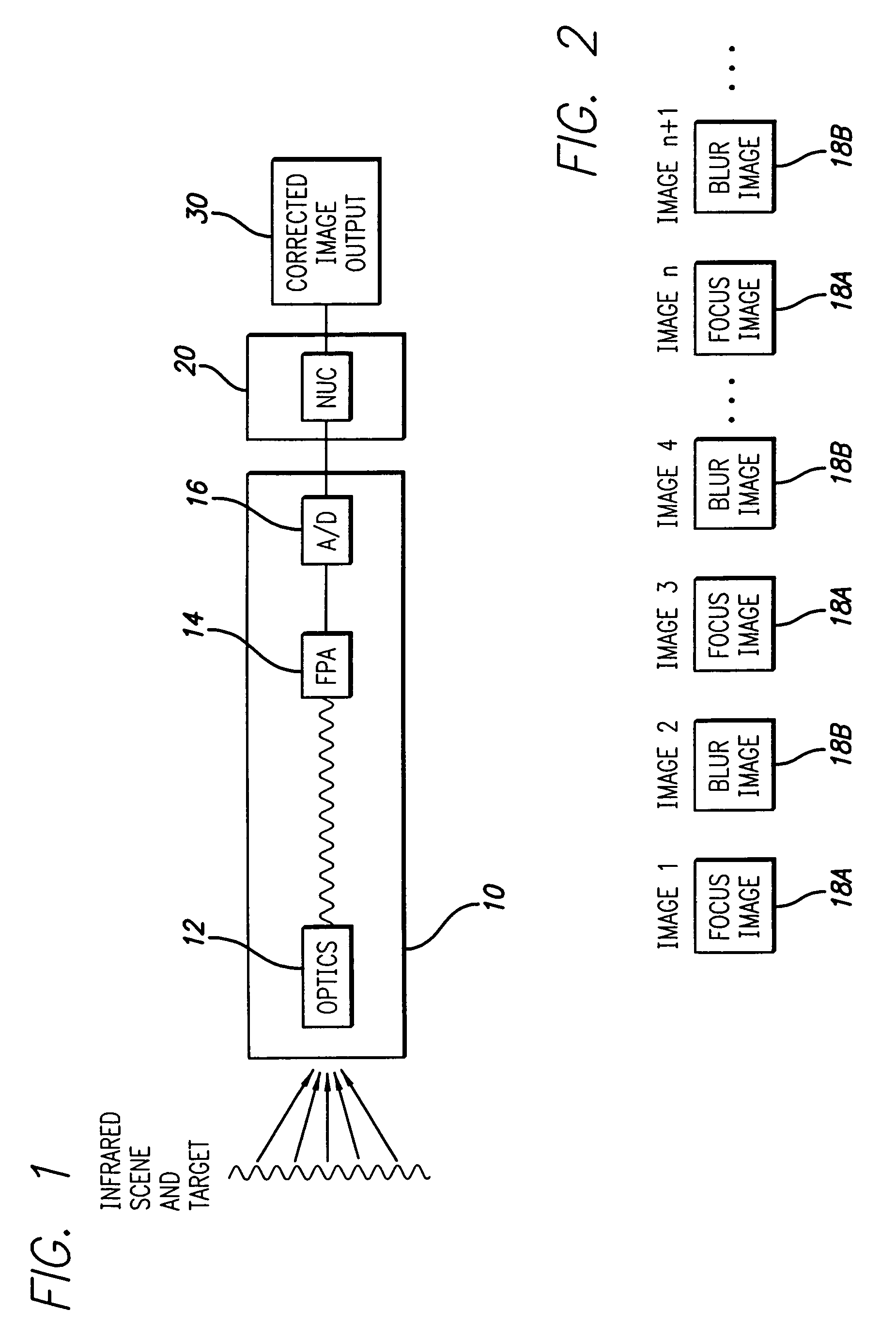
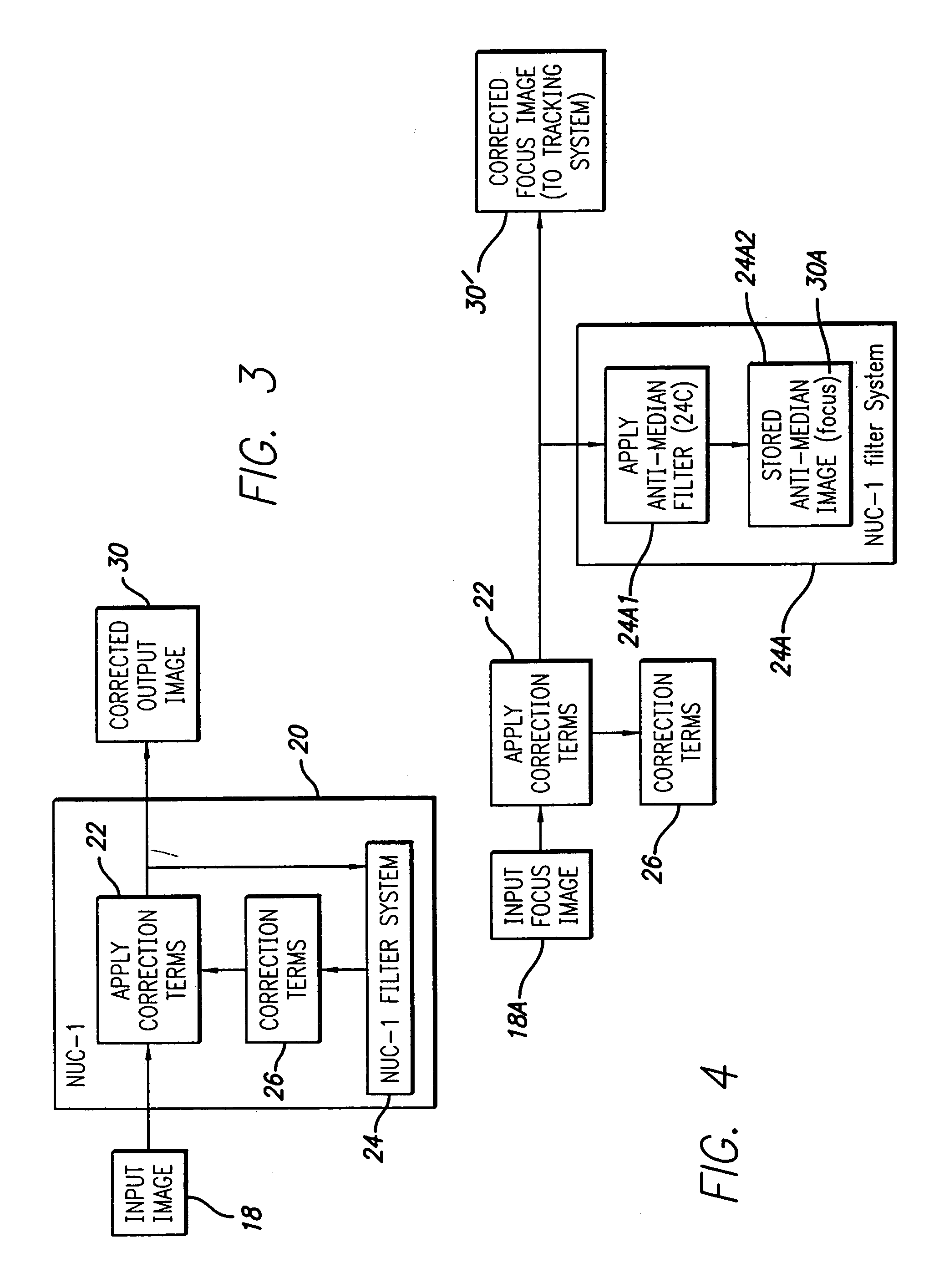
[0036]FIG. 1 is a simplified block diagram of a missile tracking system, which is disclosed in U.S. Pat. No. 5,903,659, and which includes a sensor 10 which produces an image. Typically, the sensor 10 includes optics 12 for collecting and focusing incident infrared energy from the ambient scene and target on the FPA 14, which produces an infrared ima...


PUM


Abstract

A non-traditional, non-uniformity compensation processor. In the illustrative embodiment, the feedforward adaptive non-uniformity compensation processor includes a multiplier which receives a video image and generates a compensated video image by multiplying the video signal by one of a noise reducing constant or one. The inventive processor further includes a shunting multiplication processor which supplies a selected one of the noise reducing constant or one to the multiplier in response to the presence of one of fixed pattern noise (FPN) and temporal noise (TN) in adjacent frames of the video image. In an illustrative embodiment, the inventive system cones the output of an FPA to generate a coned output signal. The system isolates the FPN in the coned output signal and feedforward processes the coned output signal on a pixel-by-pixel basis to generate a FPN-reduced output signal. In an exemplary embodiment, the feedforward processing step includes the step of multiplying the coned output signal by a predetermined value which is substantially smaller, i.e., approximately zero, than the coned output signal.

Description

BACKGROUND OF THE INVENTION[0001]1. Field of the Invention[0002]The present invention relates to systems and corresponding methods for removal of fixed pattern noise (FPN) from sensor images. More specifically, the present invention relates to systems and corresponding methods employing feedforward shunting for removal of fixed pattern noise (FPN) from sensor images.[0003]2. Description of the Related Art[0004]Focal plane arrays (FPAs) are used in various applications to capture images for subsequent processing. As disclosed in U.S. Pat. No. 5,903,659, the teachings of which are incorporated herein by reference, air-to-air missiles have employed infrared sensors with FPAs to capture infrared images of a target being tracked. The FPA typically contains n×n infrared detectors, where each detector has a slightly different sensitivity to infrared radiation. This non-uniform sensitivity yields fixed pattern noise (FPN), which manifests itself in the image, resulting in some pixels which ...

Claims


Application Information

Patent Timeline
IPC IPC(8): G06K9/03H04N5/33H04N5/365
CPCH04N5/365H04N5/33H04N25/67
Inventor CHEN, HAI-WENLO, THOMAS K.SCHMITT, HARRY A.
Owner RAYTHEON CO
Learn More