Optical wireless multiport hub

a multi-port hub and optical point-to-point technology, applied in the field of communication systems, can solve the problem that establishing new links interferes as little as possible with already established links

Inactive Publication Date: 2006-04-25
TEXAS INSTR INC
View PDF4 Cites 24 Cited by
  • Summary
  • Abstract
  • Description
  • Claims
  • Application Information

AI Technical Summary

Benefits of technology

[0008]The present invention achieves technical advantages as a receiver having distinctive retro-reflective elements and / or reflectivity that can be modulated.
[0010]The second part of the solution provides the capability to direct the remote receiver to an available port with an appropriate FOV. In the case where the retro-reflector is modulated in time, a hub port may have two distinctive modulation patterns depending on whether it is “busy”, i.e. already has established a point-to-point connection, or“free”. The “busy” pattern may be as simple as always off. The remote OWLink transmitter, upon seeking a free port, searches its FOV until it finds a free hub port. If the retro-reflective element has a FOV restricted to its transmitter's FOV, then the free hub port will always be able to find the remote OWLink port. This hub to remote link can be readily established by sending information from the remote OWLink to the hub using the transmitter light.

Problems solved by technology

In addition, it is important that the process of establishing new links interferes as little as possible with already established links.

Method used


Image

  • Optical wireless multiport hub
  • Optical wireless multiport hub
  • Optical wireless multiport hub

Examples


Embodiment Construction

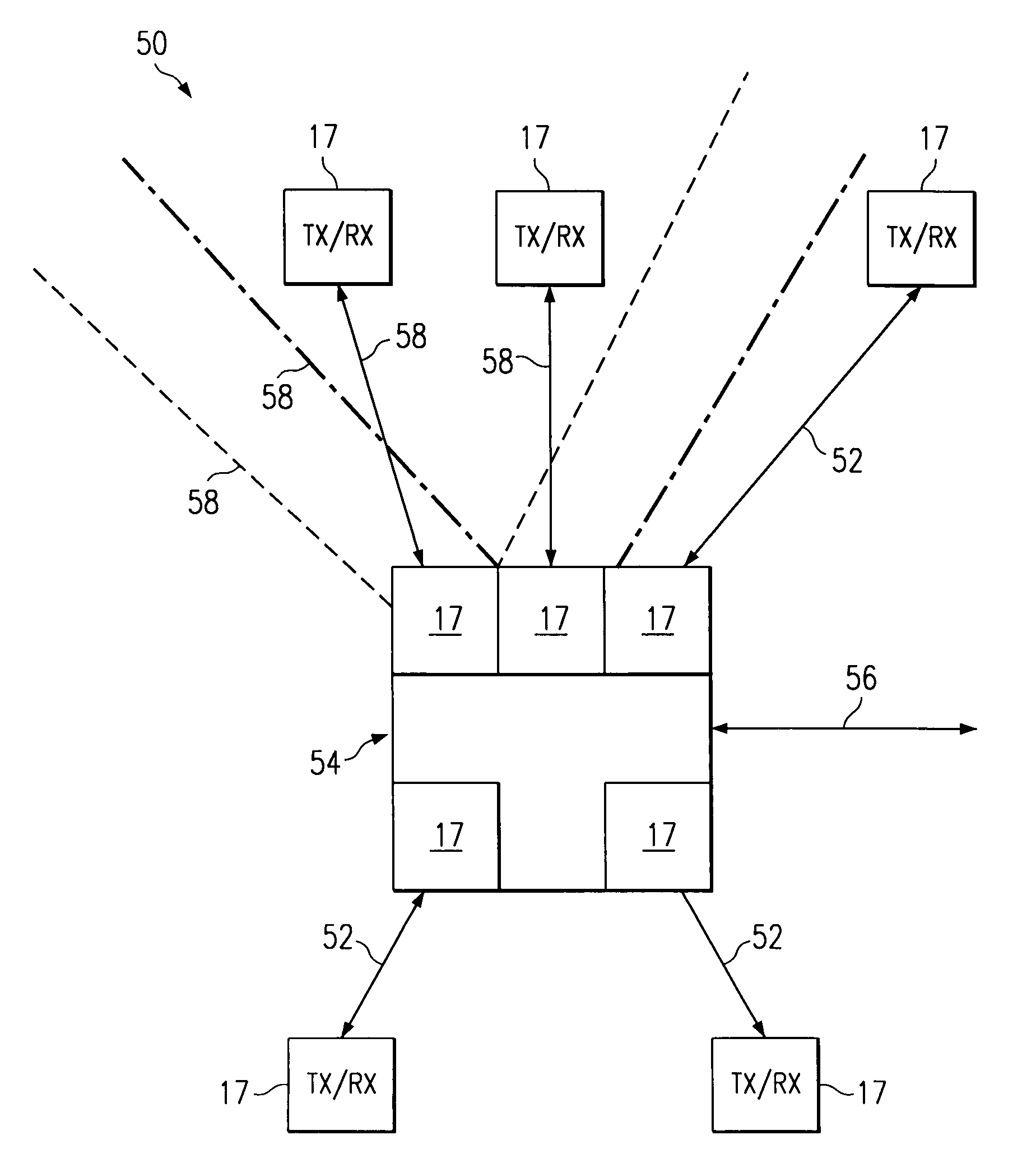
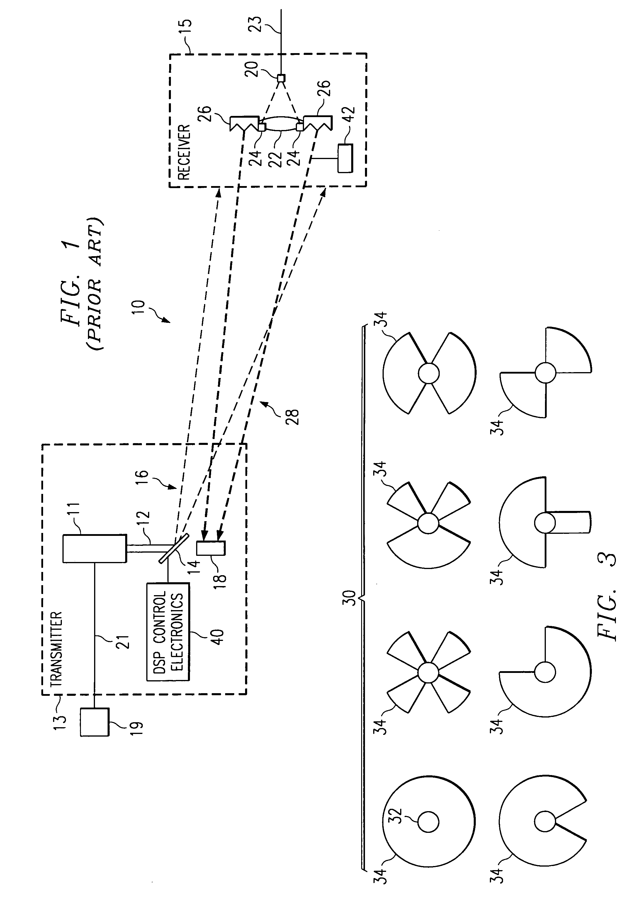
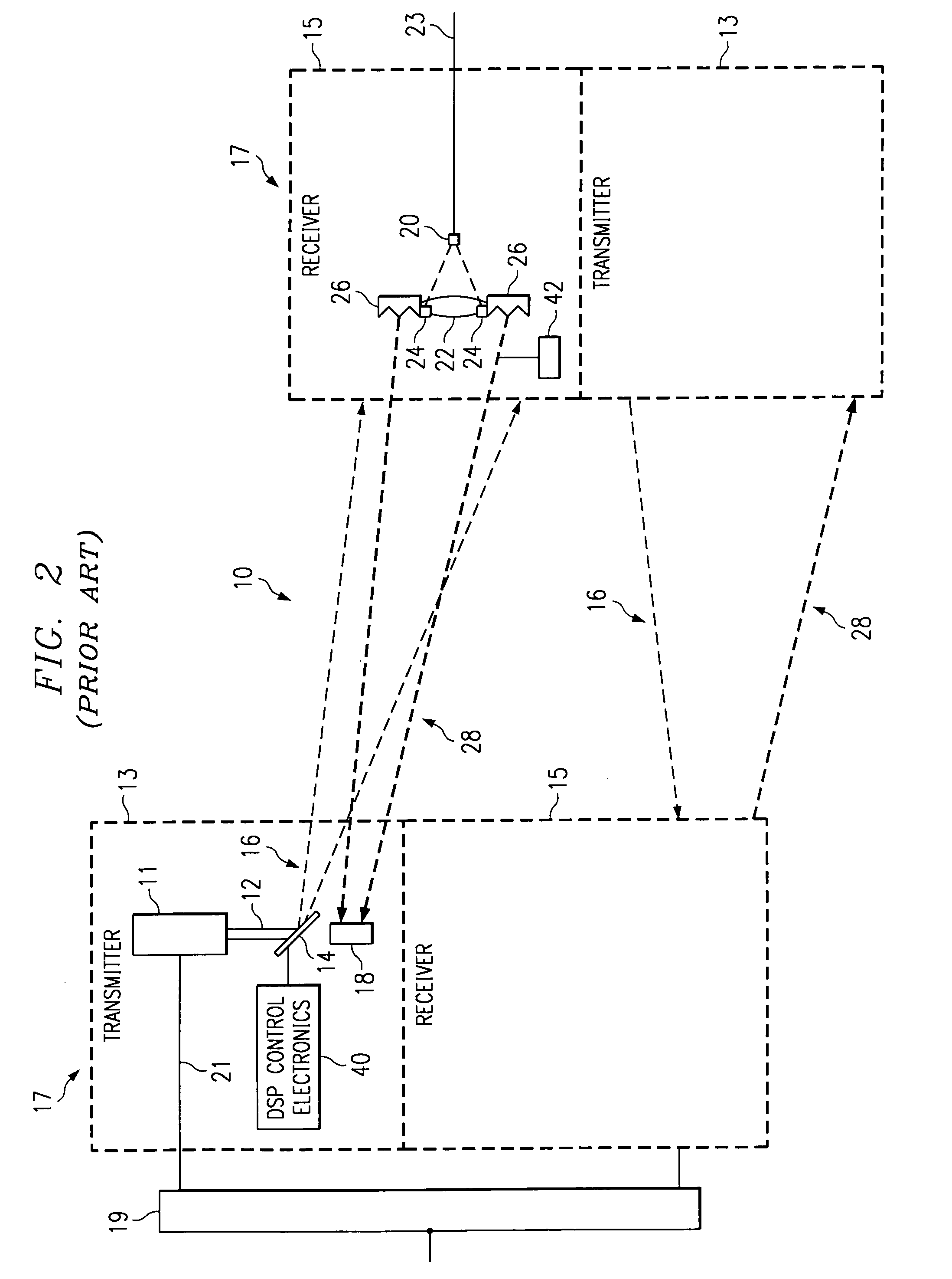
[0017]The first advantageous part of the solution provides a plurality of distinctive retro-reflective elements 30 about the optics 22 in the receiver 15 for each port in the hub. There are several solutions for creating distinctive retro-reflector elements 30. First, the retro-reflective elements 30 can have different shapes or patterns, and several examples of this are shown in FIG. 3. For each element 30 shown, the central circle 32 depicts an opening for the collection optics 22 for the associated receiver photodiode 20 and shaded portion 34 is the retro-reflective element. It is assumed that the actual corner-cube elements in the retro-reflective elements 30 are much smaller than the element itself. Advantageously, each shape shown in FIG. 3 has the property that it is distinctive from the other patterns, irrespective of rotation, translation or size.

[0018]DSP-based electronics and firmware 40 are used to controllably rotate the micromirror 14 so that the collimated beam 12 is ...


PUM


Abstract

An optical communication transmitter (13), receiver (15), and transceiver (17) having distinctive retro-reflective elements (30) and / or reflectivity that can be modulated. In one embodiment, the retro-reflective elements (30) can have different shapes or patterns (32), irrespective of rotation or size. In another embodiment, the retro-reflective elements can have their reflectivity modulated (42) to have a distinctive pattern in time. The solution also provides the capability to direct a remote optical receiver (15) to an available port (17) with an appropriate FOV. In the case where retro-reflective elements are only shape distinctive, a method may be used to direct the remote OWLink (15) to an appropriate port (17) of the hub (54). In addition to the hub ports (17) used for data links, additional hub ports called command ports (60) are added that are only used during the initial link setup of remote units. The hub (54) contains enough command ports (60) such that one command port covers each possible FOV. All command ports contain the same retro-reflective element shape that is very distinct from other hub shapes, e.g. the largest.

Description

CROSS REFERENCE TO RELATED APPLICATIONS[0001]Cross reference is made to the following co-pending patent applications, each being assigned to the same assignee as the present invention and the teachings included herein by reference: U.S. Patent application Ser. No. 60 / 234,081, entitled “Optical Wireless Network with Direct Optical Beam Pointing” filed Sep. 20, 2000; U.S. Patent application Ser. No. 60 / 285,466, entitled “Methods for Embedding Control Information Within an Optical Wireless Link” filed Apr. 20, 2001; and U.S. patent application Ser. No. 09 / 839,690 now abandoned entitled “Methods for Separating Data from Multiple Freespace Optical Sources Directed at Closely Spaced Optical Receivers” filed Apr. 20, 2001.FIELD OF THE INVENTION[0002]The present invention is generally related to communication systems, and more particularly to high data rate unidirectional and bidirectional wireless optical point-to-point systems.BACKGROUND OF THE INVENTION[0003]A point-to-point Optical Wire...

Claims


Application Information

Patent Timeline
Patent Type & Authority Patents(United States)
IPC IPC(8): H04B10/00H04B10/10H04B10/26
CPCH04B10/1121H04B10/1123H04B10/2587H04B10/1141H04B10/1125
Inventor KELLER, ROBERT C.MELENDEZ, JOSE LUIS
Owner TEXAS INSTR INC
Why Eureka
Try Eureka