On-chip signal state duration measurement and adjustment

a technology of on-chip signal and state duration, applied in the field of integrated circuits, can solve the problems of circuits that cannot function as desired, circuits such as self-resetting circuits, and circuits that have particular timing problems

Active Publication Date: 2006-04-25
ORACLE INT CORP
View PDF9 Cites 118 Cited by
  • Summary
  • Abstract
  • Description
  • Claims
  • Application Information

AI Technical Summary

Problems solved by technology

If the clock frequency increases, the longest path may not be able to fully evaluate before the next clock cycle and the circuit would not function as desired.
Other circuits, such as self-resetting circuits, have particular timing issues.
Such designs are typically very sensitive to process variations.
Also, unlike clock-based designs, where the circuit may fail at some frequency but function properly if the clock frequency decreases, once a self timed circuit fails, it fails at any clock frequency.
Some technologies are particularly susceptible to having and even developing timing problems over a period of time.
A sufficient increase in voltage thresholds can generate the self reset signal and cause variations in the pulse width of the self reset signal, which results in a hard failure at all clock frequencies.
Detecting a circuit failure caused by timing in a circuit, such as a self-resetting circuit, is very difficult using conventional technology.
Timing errors often involve on-chip signal pulse widths whose durations are either too long or too short.
However, once a timing problem is discovered, adjusting the pulse width of a signal is conventionally difficult especially for chips that have been distributed to customers.

Method used


Image

  • On-chip signal state duration measurement and adjustment
  • On-chip signal state duration measurement and adjustment
  • On-chip signal state duration measurement and adjustment

Examples


Embodiment Construction

[0021]Although the present invention has been described in detail, it should be understood that various changes, substitutions and alterations can be made hereto without departing from the spirit and scope of the invention as defined by the appended claims.

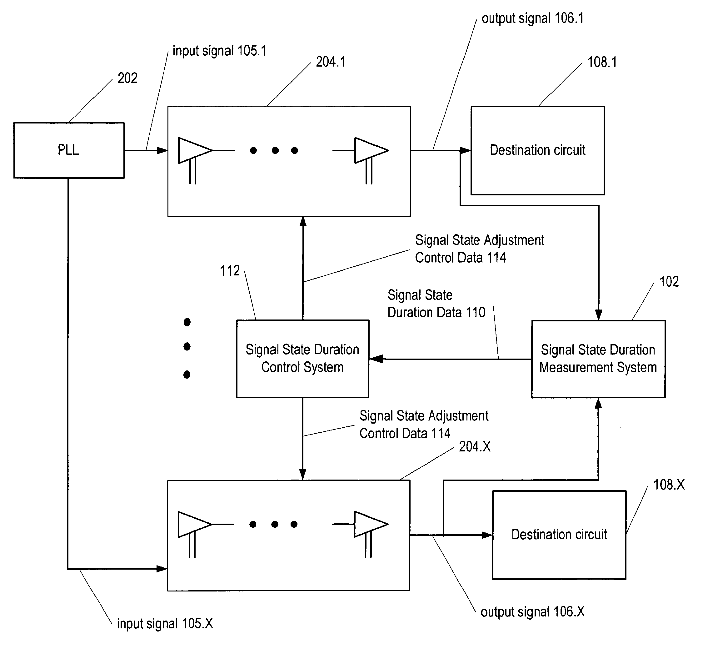
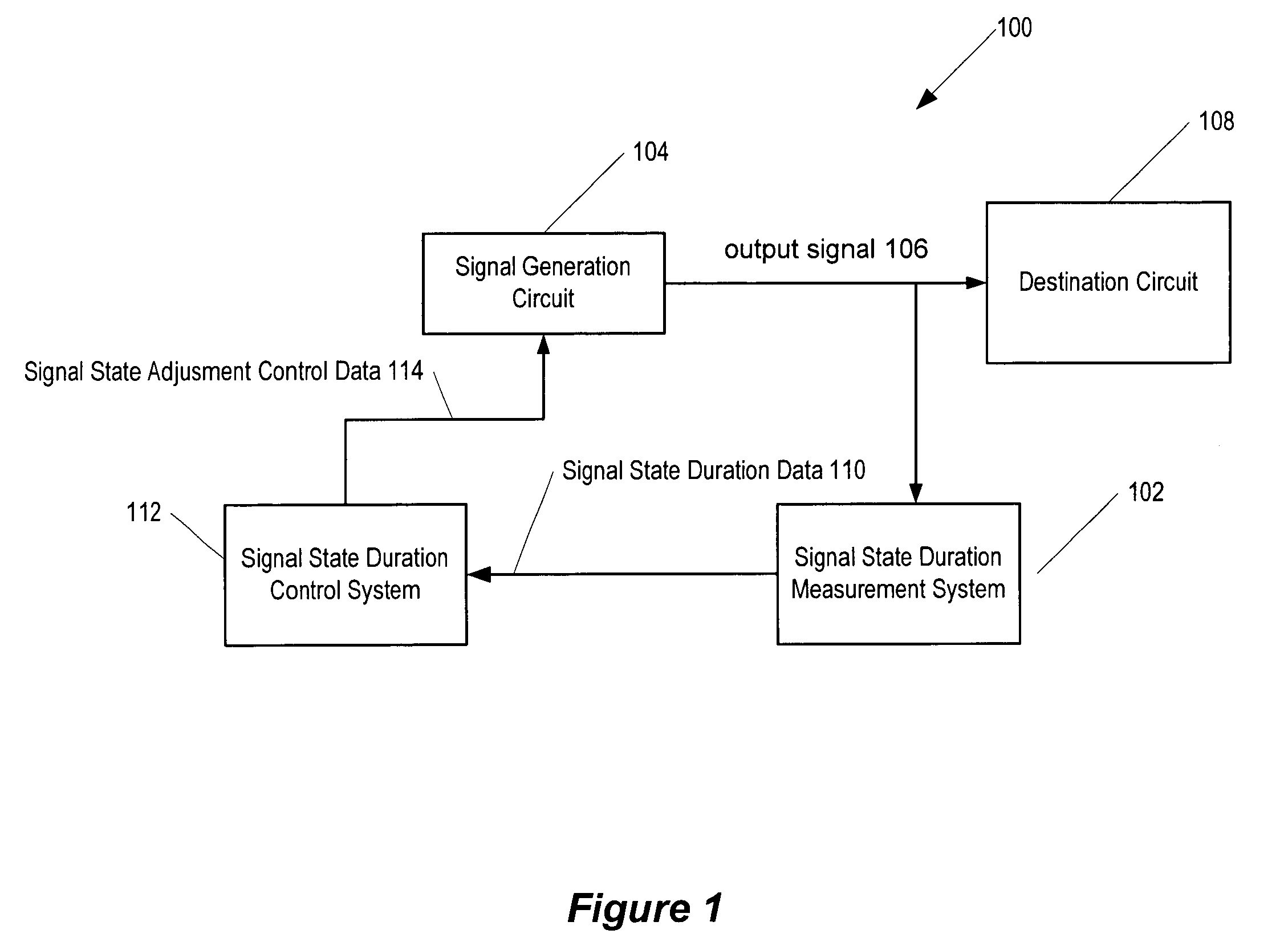
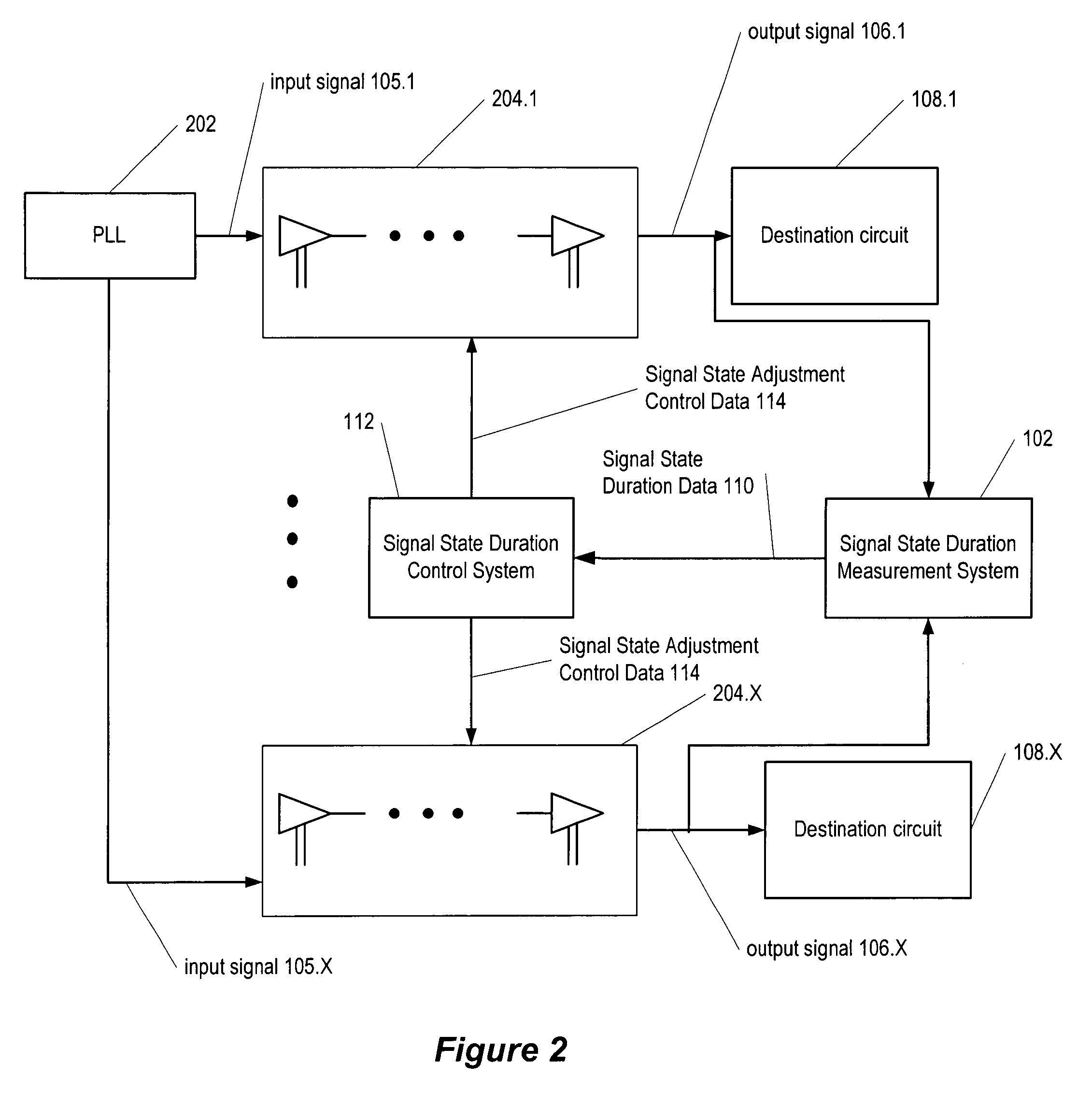
[0022]Signal state durations, such as the pulse-width, of on-chip signals are often critical to the successful operation of an integrated circuit. Commonly assigned patent application Ser. No. 10 / 292329 entitled “On-Chip Measurement of Signal State Duration”, inventors Nadeem N. Eleyan, Harsh D. Sharma, Howard L. Levy, and Hong S. Kim, which is hereby incorporated by reference in its entirety, describes examples of a signal state duration measurement system technology that measures signal state durations using on-chip technology. The signal state durations measured by on-chip technology provide signal state duration information to an on-chip signal state duration control system. The signal state duration control system uses the in...


PUM


Abstract

Signal state durations, such as the pulse-width, of on-chip signals are often critical to the successful operation of an integrated circuit. The signal state durations measured by on-chip technology provide signal state duration information to an on-chip signal state duration control system. The signal state duration control system uses the information to adjust the signal state duration of an on-chip signal. In one embodiment, the signal state duration of the on-chip signal is the pulse width of the on-chip signal. The signal duration measurement and adjustment system is, for example, useful for measuring the state duration of signals such as self-resetting signals, which are difficult to externally measure and adjust signal state durations using on-chip technology.

Description

BACKGROUND OF THE INVENTION[0001]1. Field of the Invention[0002]The present invention relates in general to the field of integrated circuits, and more specifically to a system and method for adjusting the pulse-width of an on-chip signal using an on-chip system.[0003]2. Description of the Related Art[0004]Integrated circuits typically utilize many on-chip timing and control signals. Signals have states. For example, a binary signal has high and low states, which are often referred to as “1” and “0,” respectively. Many integrated circuit designs depend on a proper duration of a signal's state for accurate performance. For example, in a flip-flop based integrated circuit design, it is typically critical to ensure that a coupled clock frequency is stable at an optimum required clock cycle to allow enough time for critical paths to fully evaluate before the next clock cycle. If the clock frequency increases, the longest path may not be able to fully evaluate before the next clock cycle ...

Claims


Application Information

Patent Timeline
Patent Type & Authority Patents(United States)
IPC IPC(8): G06F17/50G01R31/30G01R31/317G06F9/45H03K5/04
CPCG01R31/3016H03K5/04G01R31/31725
Inventor ELEYAN, NADEEM N.SHARMA, HARSH D.LEVY, HOWARD L.KIM, HONG S.
Owner ORACLE INT CORP
Why Eureka
Try Eureka