Tube-lock curtain wall system

a curtain wall and tube lock technology, applied in the field of wall framing structure, can solve the problems of insufficient insulation, relative complexity, and required relatively complicated manufacturing and assembly techniques

Inactive Publication Date: 2006-05-02
X CLAD
View PDF27 Cites 26 Cited by
  • Summary
  • Abstract
  • Description
  • Claims
  • Application Information

AI Technical Summary

Benefits of technology

[0013]Another aspect of the present invention is to avoid the need for accessory items such as joint plugs, ...

Problems solved by technology

In the past, conventional curtain wall designs have been relatively complex, have generally included multiple components, have had limited flexibility in terms of the variety of components that may be infilled in the curtain wall framework, and have thus required relatively complicated manufacturing and assembly techniques.
Conventional curtain wall designs also include flaws such as inadequate insulation, lack of structural rigidity and other drawbacks related to the aesthetic appearance thereof.
In conventional curtain walls, one such particular drawback relates to the installation procedure for glazing infill components, such as panels, doors, windows and the like, which have thus far been installable or replaceable only from one side of the curtain wall.
From a manufacturing standpoint, the manufacture of complex curtain wall designs of the past has resulted in a significant increase in the overall manufacturing cost of the frame components, which may be...

Method used


Image

  • Tube-lock curtain wall system
  • Tube-lock curtain wall system
  • Tube-lock curtain wall system

Examples


Embodiment Construction

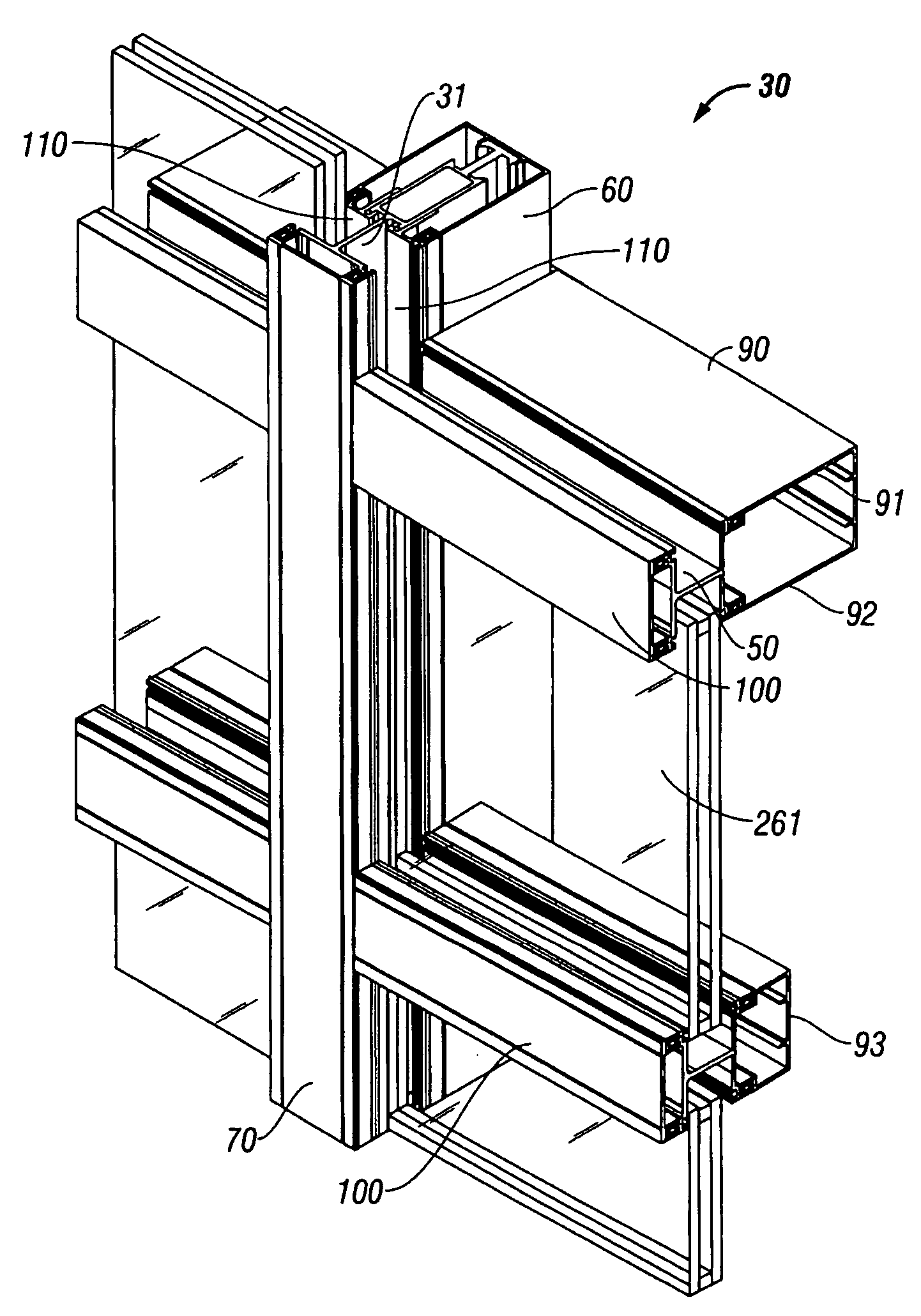
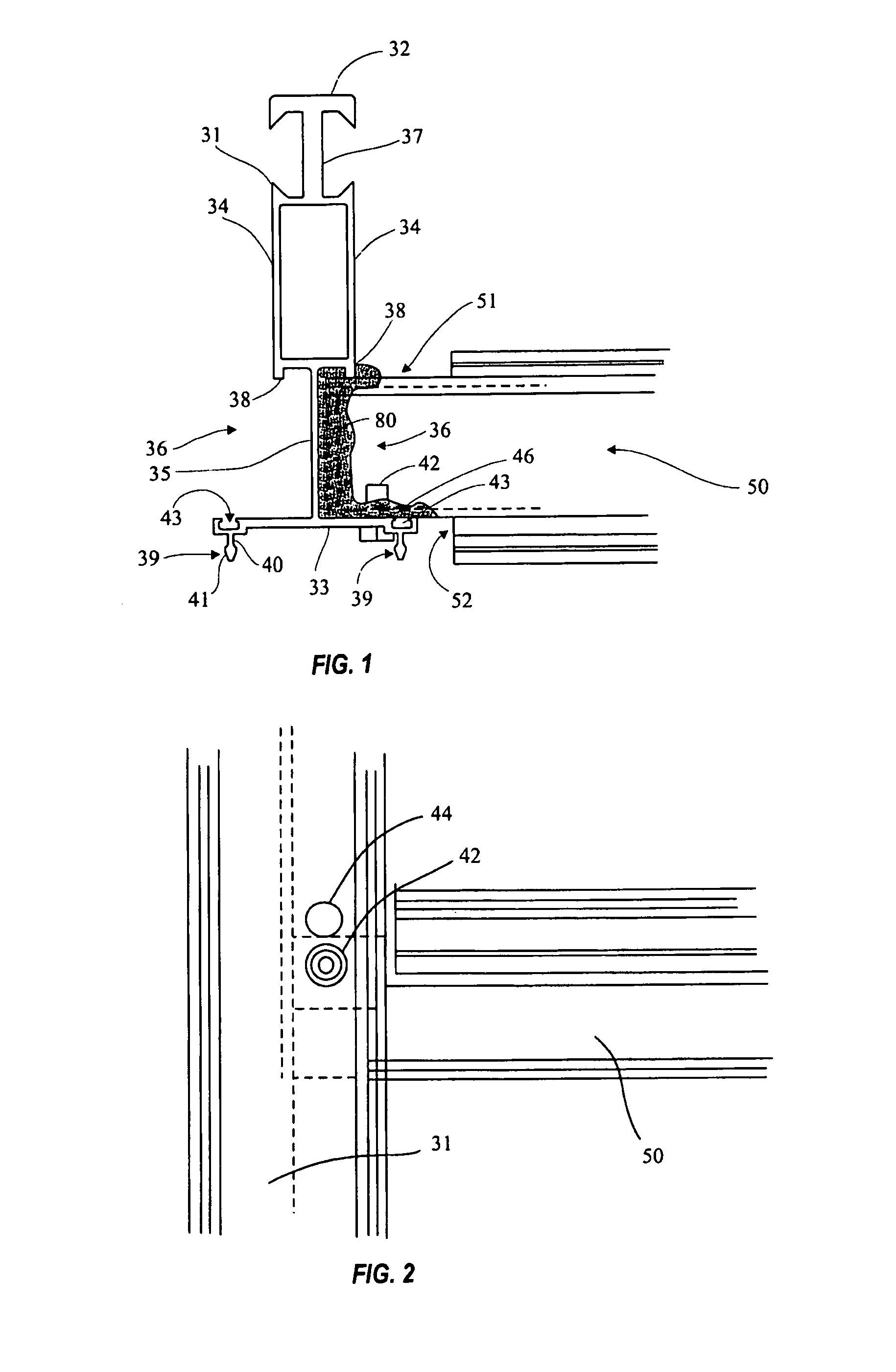
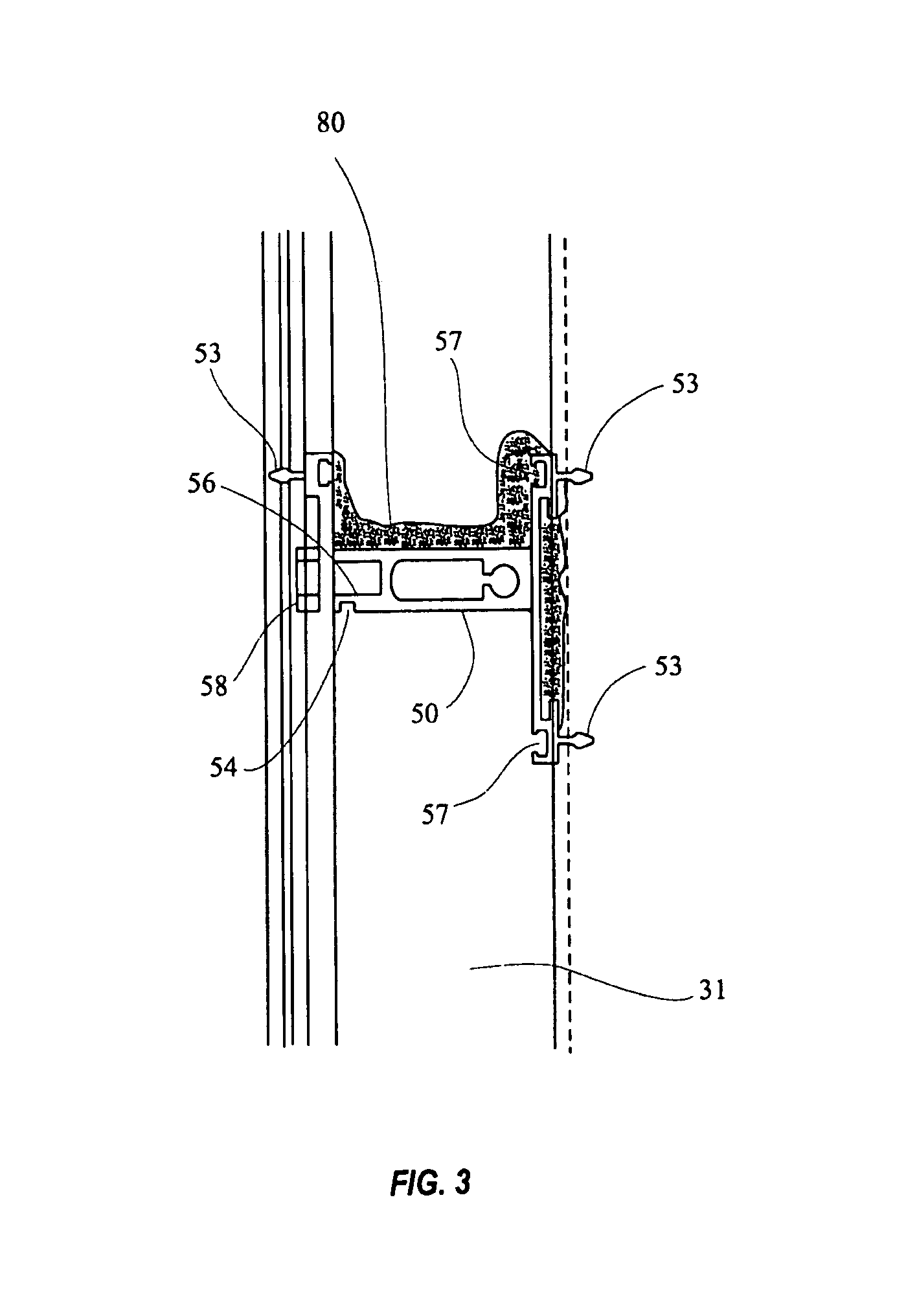
[0040]As shown in FIGS. 1 and 6, a curtain wall according to the present invention, generally designated 30, may include a mullion 31. Mullion 31 may include a front wall 32, back wall 33, side walls 34 and base portion 35. Base portion 35 may include a pair of mirror-image mullion glazing pockets 36. Mullion 31 may further include an I-section 37 and ridges 38, for connection of interior trim 60 thereto. This tubular I-beam construction provides the bending resistance of an I-Beam with the improved torsional buckling properties of a tube. A plurality of protrusions 39 may be provided for connection of exterior trim 70. Each protrusion 39 may extend substantially along the entire length of mullion 31. Moreover, as shown in FIG. 8, each protrusion 39 may include a narrow shaft section 40 and an enlarged head section 41, to permit engagement of a retention member 130, described below. At least one hole 46 may be provided on mullion 31 for insertion of a conventional screw 42 for mount...


PUM


Abstract

A curtain wall including a plurality of mullions each having a pair of glazing pockets, an I-section for supporting an interior trim member and protrusions for supporting an exterior trim member. The curtain wall further includes a plurality of rails including a notched section for insertion into the mullion glazing pockets, and a plurality of protrusions for supporting interior and exterior trim members. A bead having a plurality of protrusions is connected to the mullion in a lengthwise direction thereof, and supports the interior trim member. A plurality of retainers are insertable into notches in the mullions, the beads or the rails for removably retaining glazing infill components (i.e. panels, windows, doors) in the curtain wall. The curtain wall design of the present invention allows for the glazing infil components to be installed and/or removed from either the front side or the back side of the curtain wall.

Description

RELATED APPLICATIONS[0001]This application is a DIV of Application Ser. No. 10 / 161,735, filed Jun. 5, 2002, now U.S. Pat. No. 6,804,920.BACKGROUND OF INVENTION[0002]a. Field of Invention[0003]The invention relates generally to a wall framing structure, and, more particularly to a tube-lock curtain wall, which includes a plurality of framing components which may be interconnected to adapt the curtain wall to a variety of building structures, and incorporate therein a variety of building components such as windows, doors, panels and the like.[0004]b. Description of Related Art[0005]A need exists for an improved curtain wall system, that may be easily and economically manufactured, and that includes an improved frame network for ease of assembly and disassembly thereof, and for ease of installation.[0006]Curtain walls are well known in the art, and may be used instead of a traditional brick wall, for example, as exterior or interior walls in a building. Curtain walls generally include ...

Claims


Application Information

Patent Timeline
IPC IPC(8): E04H1/00E04H3/00E04B2/96
CPCE04B2/96
Inventor HOGAN, JERRY C.
Owner X CLAD
Why Eureka
Try Eureka