Method of operating hydrokinetic torque converters in the power trains of motor vehicles and torque converter for the practice of the method

a technology of hydrokinetic torque converter and motor vehicle power train, which is applied in the direction of fluid gearing, coupling, belt/chain/gearing, etc., can solve the problems of hydraulic fluid decomposition, disc overheating, and low degree of decomposition

Active Publication Date: 2006-05-02
SCHAEFFLER TECH AG & CO KG
View PDF7 Cites 23 Cited by
  • Summary
  • Abstract
  • Description
  • Claims
  • Application Information

AI Technical Summary

Benefits of technology

[0021]The resistance reducing step of the second undertaking can include reducing the pressure of oil by between about 0.1 and 3 bar, preferably between about 0.2 and 1 bar.
[0023]The step of hydrostatically engaging and disengaging the bypass clutch can include conveying through the bypass clutch a discrete oil stream at a pressure such that the bypass clutch is operated with slip. The discrete oil stream can constitute a pulsating stream, and the operation with slip can include minimizing torsional vibrations in a power train (such as the power train of a motor vehicle) which embodies the torque converter.

Problems solved by technology

Overheating of the discs entails damage thereto, especially if the discs are not lubricated in a required manner.
Furthermore, overheating can result in at least partial decomposition of the hydraulic fluid.

Method used


Image

  • Method of operating hydrokinetic torque converters in the power trains of motor vehicles and torque converter for the practice of the method
  • Method of operating hydrokinetic torque converters in the power trains of motor vehicles and torque converter for the practice of the method
  • Method of operating hydrokinetic torque converters in the power trains of motor vehicles and torque converter for the practice of the method

Examples


Embodiment Construction

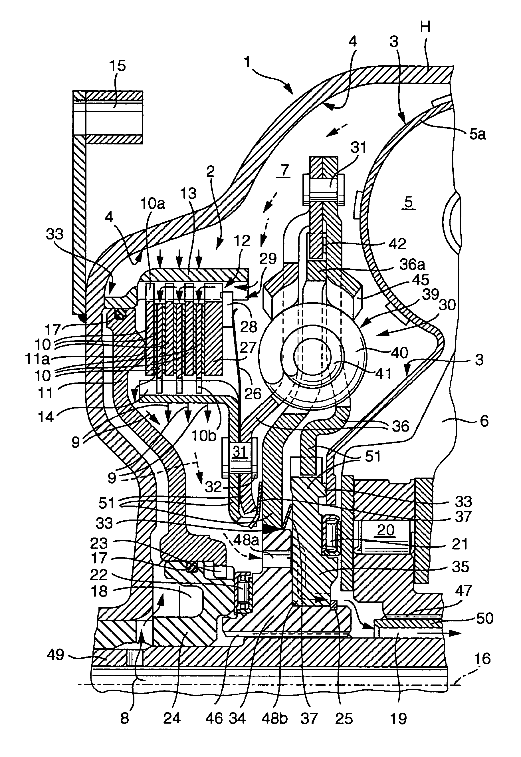
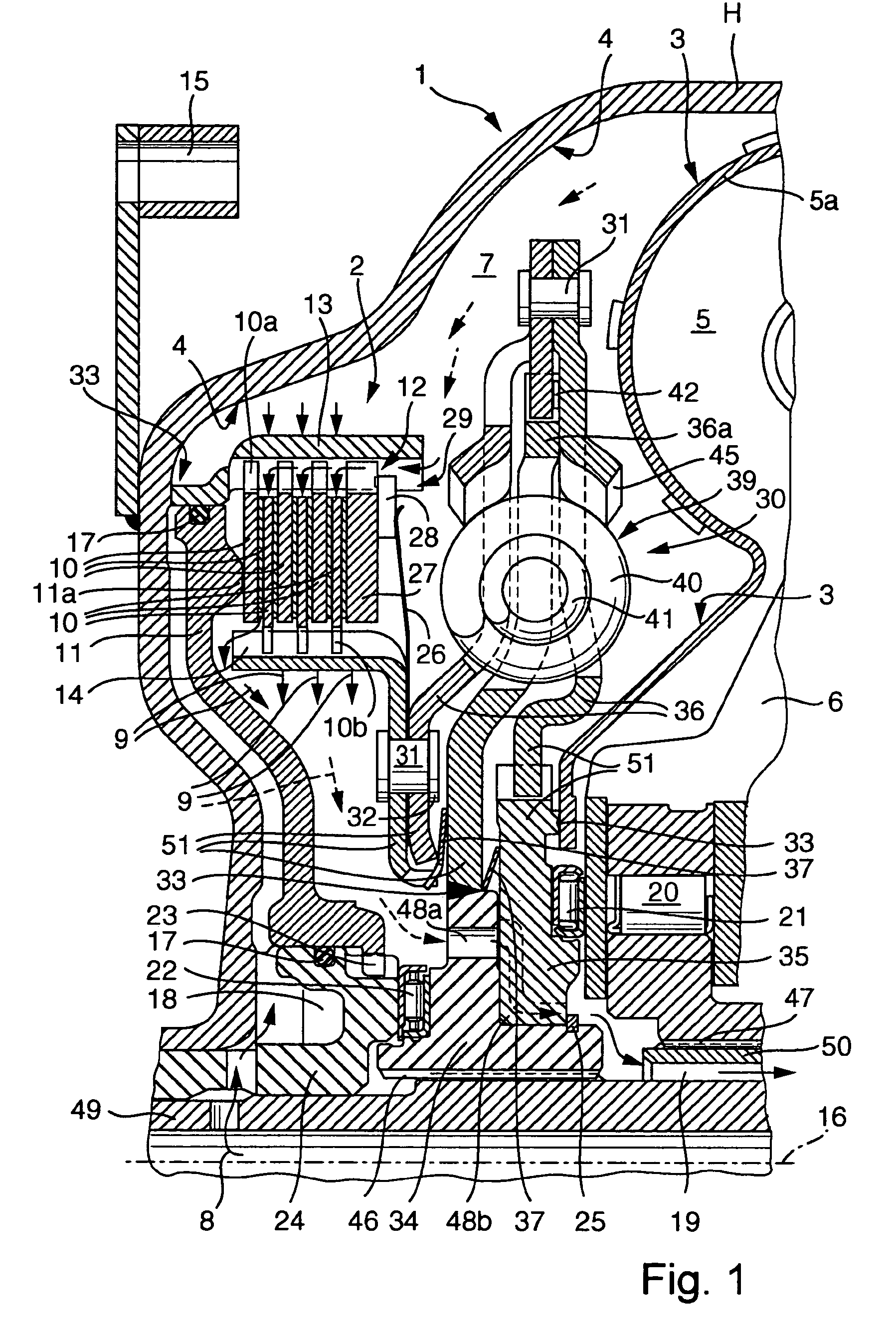
[0055]FIG. 1 illustrates certain details of a hydrokinetic torque converter 1 which is assumed to be installed in the power train of a motor vehicle, namely between the output member (such as a crankshaft or a camshaft) of a non-illustrated prime mover (e.g., an internal combustion engine or a hybrid drive) and the input shaft 49 of a change-speed transmission, not shown. The housing H of the torque converter 1 is rotatable about an axis 16 which coincides with the axis of the input shaft 49. The means for rotating the housing H includes at least one connector 15 which is rotatable with the output member of the prime mover. It will be seen that FIG. 1 is not a true engineering drawing because it shows only those portions of various component parts which are located in the plane including the axis 16; such illustration is believed to be optimally suited to properly depict the relevant component parts of the improved torque converter 1.

[0056]The connector 15 can be secured to a flywhe...


PUM


Abstract

The hydrokinetic torque converter between the prime mover and the transmission in the power train of a motor vehicle is designed to promote and / or otherwise regulate the flow of hydraulic fluid therethrough. The fluid is circulated between the friction linings on the laminations of the bypass clutch in the housing of the torque converter. In a first embodiment of the method, the flow of fluid in certain parts of the torque converter is opposed or interfered with in such a way that a larger quantity of fluid flows between the laminations of the bypass clutch. In a second embodiment, the resistance to fluid flow through the bypass clutch of the torque converter is reduced. It is also possible to resort to both solutions in one and the same torque converter.

Description

BACKGROUND OF THE INVENTION[0001]The invention relates to improvements in hydrokinetic torque converters, especially for use in the power trains of motor vehicles, and to improvements in methods of operating such torque converters.[0002]A hydrokinetic torque converter which is utilized in the power train of a motor vehicle forms part of an operative connection between the prime mover (such as an internal combustion engine or a hybrid drive) and the change-speed transmission. Reference may be had, for example, to commonly owned U.S. Pat. No. 5,782,327 granted Jul. 21, 1998 to Otto et al. for “HYDROKINETIC TORQUE CONVERTER AND LOCKUP CLUTCH THEREFOR”, as well as to the publications which are discussed in the specification of this patent. The efficiency of the torque converter can be enhanced by resorting to a so-called bypass or lockup clutch which, as a rule, becomes engaged when the ratio of the RPM of the turbine to the RPM of the pump in the housing of the torque converter is betw...

Claims


Application Information

Patent Timeline
Patent Type & Authority Patents(United States)
IPC IPC(8): F16H45/02
CPCF16H45/02F16H2045/021F16H2045/0284F16H2045/0247F16H2045/0215
Inventor BACK, GUNNARHONEMANN, RUDOLFMAIENSCHEIN, STEPHAN
Owner SCHAEFFLER TECH AG & CO KG
Why Eureka
Try Eureka