
Anti-lock braking system of motorcycle

An anti-lock braking system and oil circuit technology, applied to vehicle components, bicycle accessories, bicycle brakes, etc., can solve the problems of motorcycles losing steering ability, wheel locking, and prone to traffic accidents

Inactive Publication Date: 2015-03-11
ZHEJIANG CFMOTO POWER CO LTD
View PDF3 Cites 6 Cited by
  • Summary
  • Abstract
  • Description
  • Claims
  • Application Information

AI Technical Summary

Problems solved by technology

[0003] However, if the braking force generated by the front and rear wheel brake calipers is too large, the phenomenon of wheel lock is prone to occur.
If the front wheel is locked, the motorcycle will lose the ability to turn. If the rear wheel is locked, the motorcycle is prone to skidding and flicking, which is very prone to traffic accidents.

Method used


Image

  • Anti-lock braking system of motorcycle
  • Anti-lock braking system of motorcycle
  • Anti-lock braking system of motorcycle

Examples


Embodiment 1

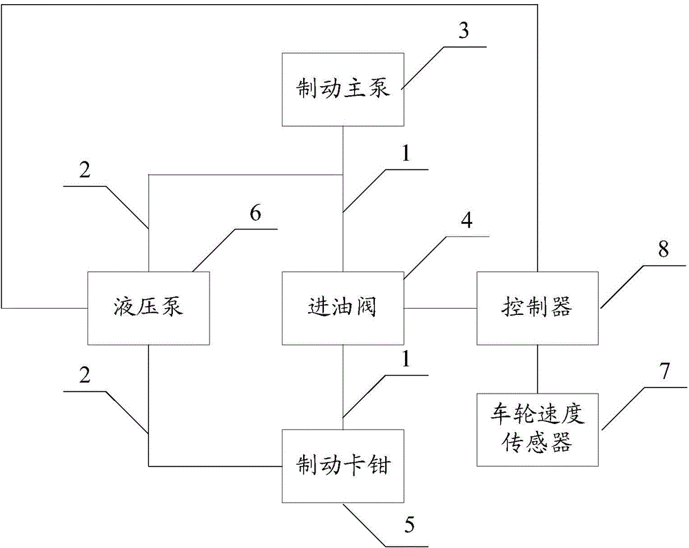
[0030] see figure 1 A structural schematic diagram of an embodiment of a motorcycle anti-lock braking system according to the present invention is shown.

[0031] Depend on figure 1 It can be seen that, in this embodiment, the system is composed of a main circulating oil circuit 1 and a secondary circulating oil circuit 2 . Wherein, the main circulating oil circuit 1 includes: a main brake pump 3 , an oil inlet valve 4 communicated with the main brake pump 3 , and a brake caliper 5 communicated with an oil outlet of the oil inlet valve 4 .

[0032] During normal braking, the brake fluid output by the main brake pump 3 flows along the main circulation oil circuit 1 , that is, flows into the brake caliper 5 through the oil inlet valve 4 . Since the brake caliper 5 is a hydraulic brake, when the brake fluid flows into the brake caliper, the brake fluid pushes the piston of the brake caliper 5 to move, thereby achieving the purpose of braking. It should be noted that the specif...

Embodiment 2

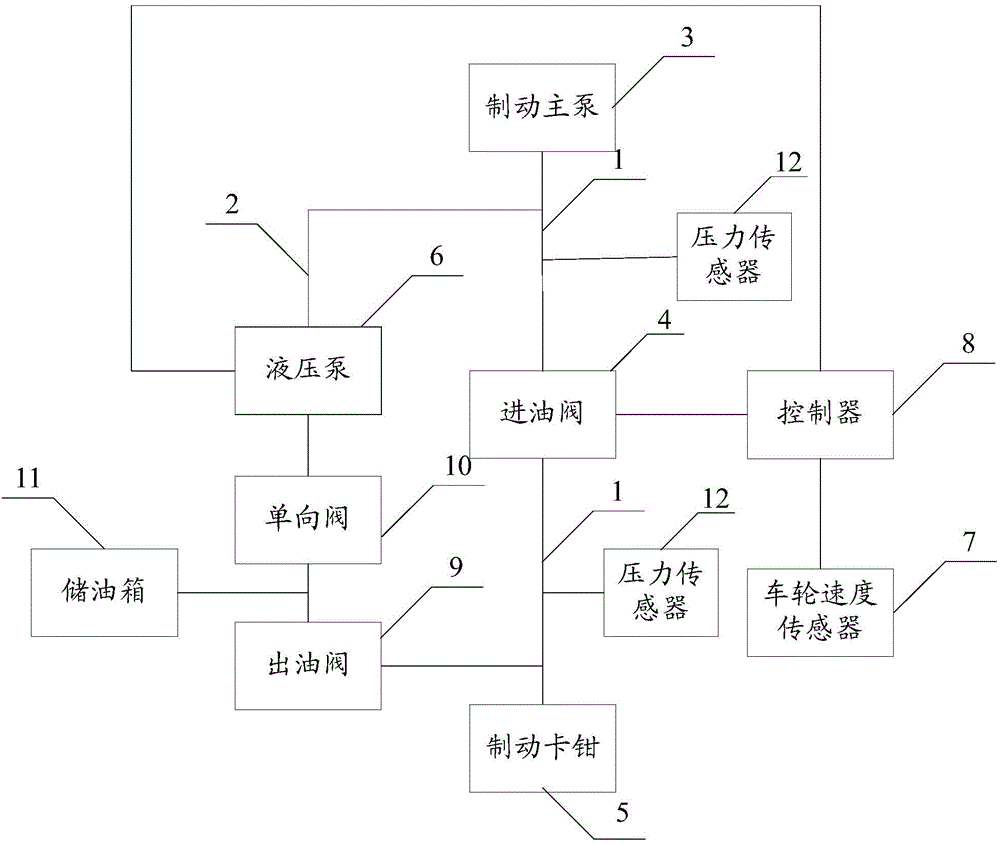
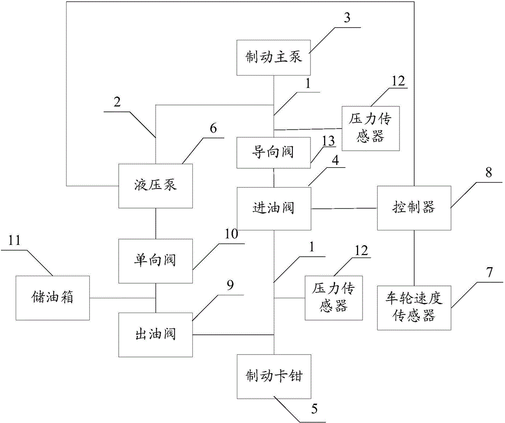
[0039] see Figure 2 to Figure 3 , figure 2 A schematic structural view of a front brake unit of a motorcycle anti-lock braking system according to the present invention is shown, image 3 A schematic structural view of a rear braking unit of a motorcycle anti-lock braking system according to the present invention is shown.

[0040] In practical applications, since motorcycle braking includes front braking and rear braking, that is, using the front brake handle for braking and the rear brake pedal for braking, the anti-lock braking system in the present invention is also correspondingly The includes front brake unit and rear brake unit.

[0041] Wherein, the main circulating oil circuit 1 of the front brake unit includes: a main brake pump 3 , an oil inlet valve 4 communicating with the main brake pump 3 , and a brake caliper 5 communicating with an oil outlet of the oil inlet valve 4 .

[0042] The secondary circulation oil circuit 2 includes: a hydraulic pump 6 and an oi...


PUM


Abstract

The invention discloses an anti-lock braking system of a motorcycle. The system mainly comprises a main circulating oil path and a secondary circulating oil path, wherein brake fluid output by a brake main pump flows by an oil inlet valve into a pair of brake calipers through the main circulating oil path during normal brake; the pair of brake calipers realizes hydraulic brake under the action of oil pressure; when a controller determines that wheels are in a to-be-locked state through a wheel speed sensor, the controller controls the oil inlet valve to be closed, the brake fluid does not flow into the brake calipers, then the controller controls a hydraulic pump to be turned on, and the hydraulic pump pumps the brake fluid in the brake calipers back into the brake main pump through the secondary circulating oil path, so that the oil pressure in the brake calipers is reduced and the locking of the wheels is prevented.

Description

technical field [0001] The invention relates to the field of motorcycles, in particular to an anti-lock braking system for motorcycles. Background technique [0002] The braking of the motorcycle in the running process is to control the front and rear wheel brake calipers to generate braking force by manually operating the front brake handle or the rear brake pedal to brake the front and rear wheels. [0003] However, if the braking force generated by the front and rear wheel brake calipers is too large, the phenomenon of wheel lock is prone to occur. If the front wheels are locked, the motorcycle will lose its ability to turn, and if the rear wheels are locked, the motorcycle will easily slip and flick, and traffic accidents will easily occur. Contents of the invention [0004] In view of this, the present invention discloses an anti-lock braking system for a motorcycle, which can effectively prevent the front and rear wheels of the motorcycle from locking and reduce the...

Claims


Application Information

Patent Timeline
IPC IPC(8): B62L3/08B60T8/34B60T8/176
CPCB62L3/08B60T8/176B60T8/344
Inventor 赖国贵袁章平陈志勇王昌伟丁冬
Owner ZHEJIANG CFMOTO POWER CO LTD
Learn More