Oil pressure controlled vehicle transmission, power unit incorporating same, and method of using same

Active Publication Date: 2007-08-30
HONDA MOTOR CO LTD
View PDF24 Cites 8 Cited by
  • Summary
  • Abstract
  • Description
  • Claims
  • Application Information

AI Technical Summary

Benefits of technology

[0009] According to the first aspect of the invention, at the time of starting from the neutral condition, the oil pressure in the hydraulic clutch for transmitting power from the crankshaft to the starting gear train is maintained in a lowered state and is thereafter increased in response to complete engagement of the starting gear train. Therefore, the transmission of power between the gear train and the crankshaft is perfectly interrupted at the time when the starting gear train is engaged, so that a shock can be prevented from being generated at the time of starting.
[0013] According to the third aspect of the invention, shocks at the times of forward-side starting and reverse-side starting can be eliminated by the single control valve.

Problems solved by technology

Therefore, when the oil pressure acts on the hydraulic clutch, even though the hydraulic clutch is not in a perfect connected state, a speed change shock is generated due to drag of the hydraulic clutch.

Method used


Image

  • Oil pressure controlled vehicle transmission, power unit incorporating same, and method of using same
  • Oil pressure controlled vehicle transmission, power unit incorporating same, and method of using same
  • Oil pressure controlled vehicle transmission, power unit incorporating same, and method of using same

Examples


Embodiment Construction

[0028] Selected illustrative embodiments of the invention will now be described in some detail, with reference to the drawings. It should be understood that only structures considered necessary for clarifying the present invention are described herein. Other conventional structures, and those of ancillary and auxiliary components of the system, are assumed to be known and understood by those skilled in the art.

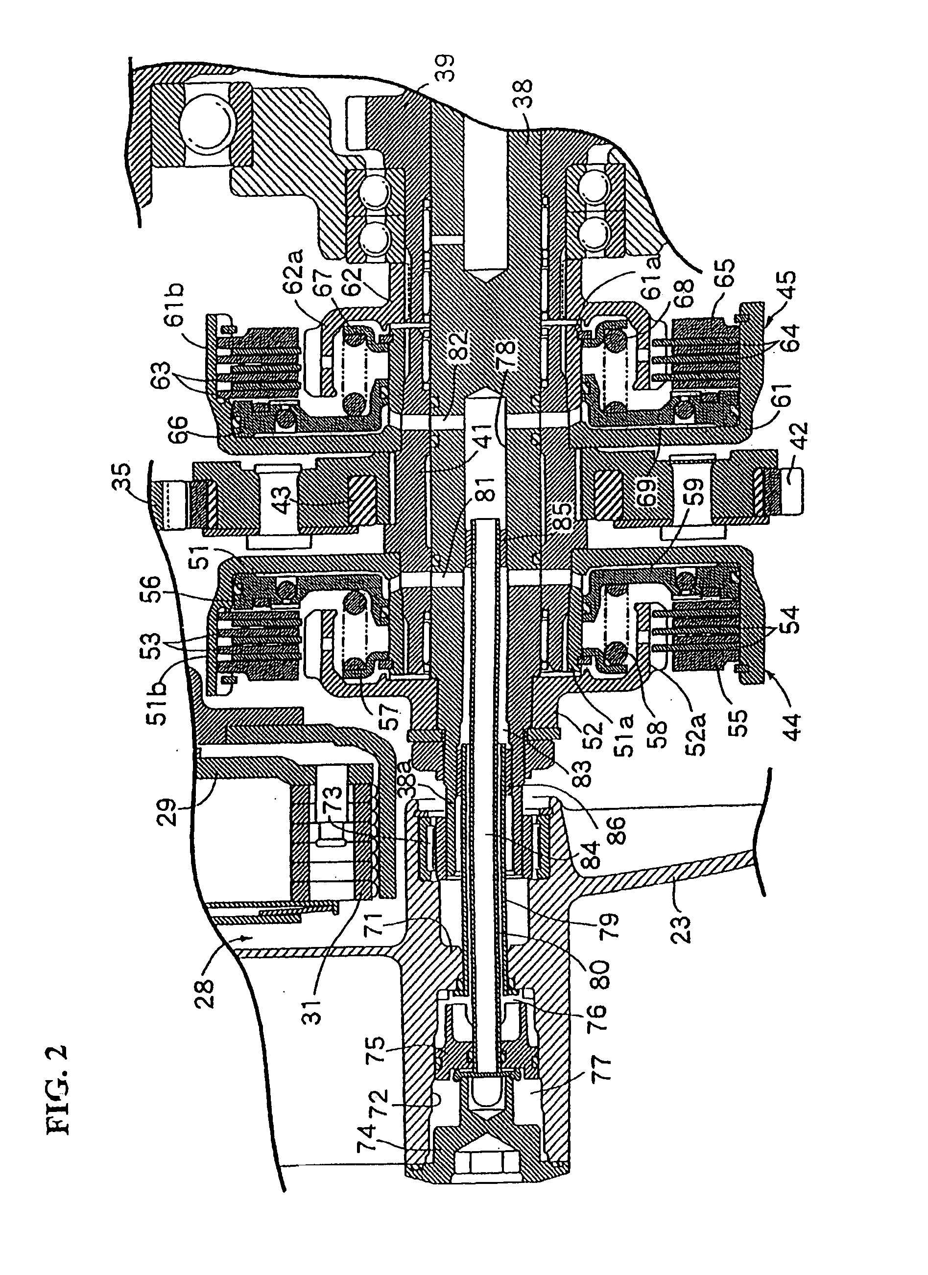
[0029] FIGS. 1 to 7 show a number of views of a power unit including a transmission according to an illustrative embodiment of the present invention.

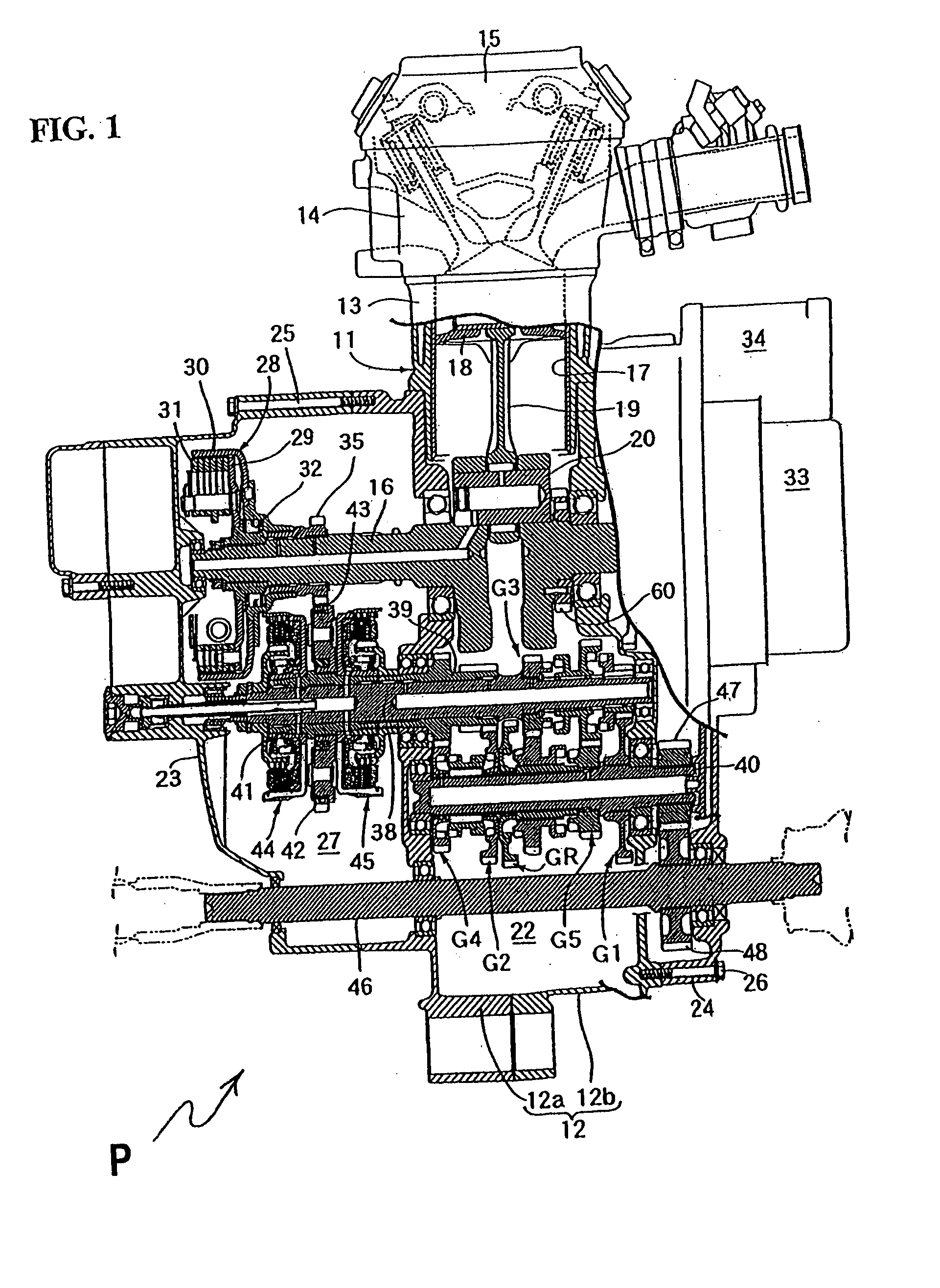
[0030] First, in FIG. 1, a power unit P is adapted to be mounted on a vehicle. The power unit P is an integrated and combined engine and transmission assembly, including a hollow crankcase 12 having many other components mounted therein. The power unit P further includes an engine body 11 in which the crankcase 12 rotatably supports a crankshaft 16 thereon, and a cylinder block 13 is connected to an upper portion of the crankcas...


PUM


Abstract

A transmission for a vehicle is provided which prevents generation of a speed change shock at the time of starting the vehicle from a neutral condition. In the transmission, hydraulic clutches are each put into a connected state according to an action of an oil pressure, and a plurality of selectively engageable speed-stage gear trains are provided so that a neutral condition can be obtained. At the time of shifting from the neutral condition, where the oil pressures in hydraulic clutches are in a lowered state, to a starting condition in which a starting gear train is engaged, pressure in the hydraulic clutch corresponding to the starting gear train is controlled by a control valve, so that the oil pressure in the hydraulic clutch is maintained in the lowered state during and immediately after a shifting operation, and is subsequently increased in response to complete engagement of the starting gear train.

Description

CROSS-REFERENCE TO RELATED APPLICATIONS [0001] The present invention claims priority under 35 USC 119 based on Japanese patent application No. 2006-053844, filed on Feb. 28, 2006. The entire subject matter of this priority document, including specification, drawings, and claims, is incorporated by reference.BACKGROUND OF THE INVENTION [0002] 1. Field of the Invention [0003] The present invention relates to a transmission for a vehicle wherein hydraulic clutches are provided between a crankshaft and main shafts of an power unit, each hydraulic clutch being put into a connected state by adjustment of oil pressure therein, and wherein a plurality of selectively connectable speed-stage gear trains are provided between a transmission output shaft and the main shafts in such a manner that a neutral condition can be obtained. [0004] 2. Description of the Background Art [0005] A conventional transmission for a vehicle includes a plurality of speed-stage gear trains divided into two groups. ...

Claims


Application Information

Patent Timeline
IPC IPC(8): B60W10/02B60W10/10F16H59/04F16H61/06F16H61/68F16H61/682F16H61/684F16H61/688
CPCF16H61/0437F16H61/688F16H2312/022F16H2061/0488F16H2312/02F16H2061/0485F16D48/062F16D2021/0623F16D2048/0203F16D2048/0266
Inventor MIZUNO, KINYAFUJIMOTO, YASUSHIHAMAOKA, SEIJIKITTAKA, EIJI
Owner HONDA MOTOR CO LTD
Why Eureka
Try Eureka