Conveyor chain

Inactive Publication Date: 2006-05-02
ROBINSON CHRISTOPHER J
View PDF12 Cites 26 Cited by
  • Summary
  • Abstract
  • Description
  • Claims
  • Application Information

AI Technical Summary

Benefits of technology

[0011]The method of this invention produces a steel conveyor chain link having a p

Problems solved by technology

In the grain industry, sparks can ignite grain dust explosions.
Unfortunately, the polymeric links are much more expensive than steel links and they are not nearly as strong.
Furthermore, the flights wear much more rapidly than steel flights.
However, w

Method used


Image

  • Conveyor chain
  • Conveyor chain
  • Conveyor chain

Examples


Embodiment Construction

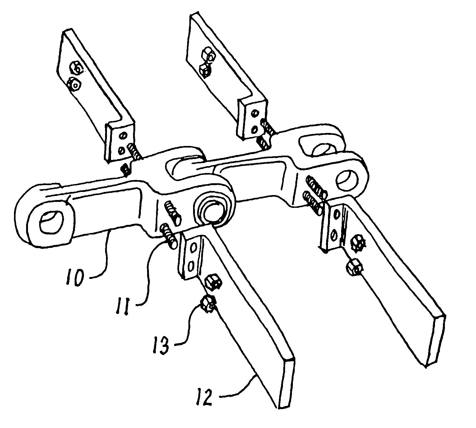
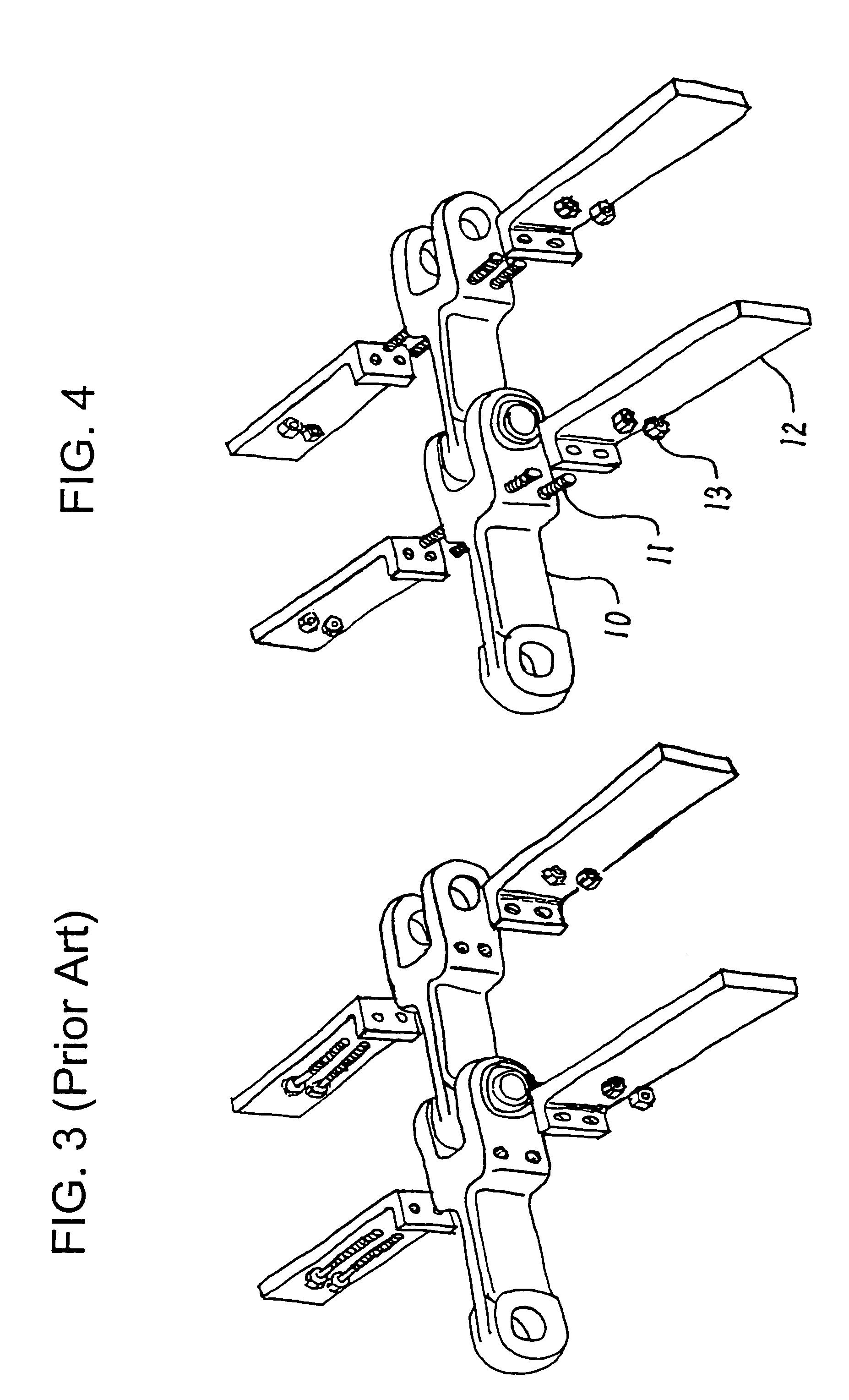
[0016]This invention is best understood by reference to the drawings. Two steel conveyor chain links 10 that have no flights are shown in FIG. 4. The links shown are of the fork link type. Other types of chains, including double strands, combination strands, and the like, are equally suitable.

[0017]Welded to each side of each link are two threaded studs 11. The studs are readily available articles of commerce. They are made of steel and generally have a length of about one inch and a diameter of about three-eighths inch. They are oriented in a latitudinal direction, perpendicular to the direction of travel of the chain. The studs on each side are preferably positioned in the same vertical plane, in other words, one is mounted directly above the other. Three or more studs can be welded to each side, but the additional studs add to the cost.

[0018]The studs are preferably welded to the link using the conventional stud welding process in which opposing electrical charges are created on ...


PUM


Abstract

A steel conveyor chain link having a polymeric flight is produced by obtaining a flightless steel conveyor chain link, obtaining a threaded stud, obtaining a polymeric flight having a mounting base, positioning the threaded stud against the link in a latitudinal orientation, welding the threaded stud onto the link, and fastening mounting base of the polymeric flight onto the stud.

Description

CROSS-REFERENCE TO RELATED APPLICATION[0001]This application claims the benefit of U.S. Provisional Application Ser. No. 60 / 545,075, Feb. 17, 2004.FIELD OF THE INVENTION[0002]This invention relates to the movement of bulk and granular materials. More particularly, this invention relates to conveyor chains for moving such materials.BACKGROUND OF THE INVENTION[0003]Conveyors are continuous moving belts that transport bulk and granular materials from one place to another. In some types of conveyors, the material travels on the belt itself. In other types of conveyors, buckets or flights are attached to the moving belt. An example of the latter type is a conveyor chain in which the belt is formed of multiple chain links, some or all of which contain flights. As the conveyor chain moves along inside an enclosed duct, the flights pull a cross-section of material along with it. Two links of a conventional fork link conveyor chain are shown in FIG. 1. The direction of travel of the conveyor...

Claims


Application Information

Patent Timeline
IPC IPC(8): B65G19/24
CPCB65G19/24B65G19/08
Inventor ROBINSON, CHRISTOPHER J.
Owner ROBINSON CHRISTOPHER J
Why Eureka
Try Eureka