Method and device for inserting a drainage wick

a drainage wick and wick inserting technology, which is applied in the direction of irrigation ditches, soil drainage, soil preservation, etc., can solve the problems of increasing the cost, increasing the cost, and reducing the efficiency of the drainage wick, so as to achieve non-slowing process and inexpensive

Inactive Publication Date: 2009-07-28
FREIXENET SA
View PDF33 Cites 2 Cited by
  • Summary
  • Abstract
  • Description
  • Claims
  • Application Information

AI Technical Summary

Benefits of technology

[0012]It is an object of the invention to resolve the problems of anchorage component positioning and avoiding such previously described drawbacks with an inexpensive and non slowing process solution.
[0020]During the step of pulling up the inserting tube and drainage wick, the anchorage component is not pulled up and can easily remain lodged in position in the ground. The soil around the anchorage component can rearrange and apply an hydrostatic pressure on the anchorage component so that the anchorage component remains in its position when the tie is tightened and the drainage wick pulls on it during the step of further pulling up the inserting tube.
[0025]A complementary feature to the method comprises the step of introducing compressed air in the inserting tube after the drainage wick jamming step. Introducing compressed air in the inserting tube enables pushing an anchorage component downwardly in the soil and makes its anchorage easier. Such a process is faster and less expensive than known processes where water is used to hold down an anchorage component.
[0030]According to still another feature of embodiments of the invention, the method comprises the step of filling the soil zone around the anchorage component with a sealing or retention material such as mud, clay or water expandable material, such as bentonite, water activated polymer, before and / or when the inserting tube and the drainage wick are pulled up and before the drainage wick is permitted to remain in the soil. It is then possible to further rearrange the soil during the step of pulling up the inserting tube and drainage wick and seal the soil around the anchorage component and / or the tie. Furthermore when water expandable material is used, water of the soil contacts the water expandable material which expands in volume and enhances the sealing and maintenance of the anchorage component into the soil.

Problems solved by technology

It has to be noted that while such a process is widely and commonly used, drawbacks still exist; namely, when the drainage wick needs to be inserted deeply and / or in soft soils.
The efficiency of the drainage wick is then considerably reduced and in extreme cases annihilated if it is pulled out of the soil layer to be drained.
First it increases the costs, due mainly to deeper installation and slowing down the wick drainage installation process.
Second, such a process may be unusable due to geological constraint, such as aquifer presence in the hard soil.
However, the use of such large anchorage components increases cost of such a component and significantly increases penetration resistance of the soil when installing the drainage wick.introducing water in the inserting tube to balance hydrostatic pressure at the bottom of the inserting tube and then pushing the anchorage component in the soil, allowing it to remain in the bottom position.
However, such water filling of the inserting tube is time and energy consuming and is generally to be avoided.

Method used


Image

  • Method and device for inserting a drainage wick
  • Method and device for inserting a drainage wick
  • Method and device for inserting a drainage wick

Examples


Embodiment Construction

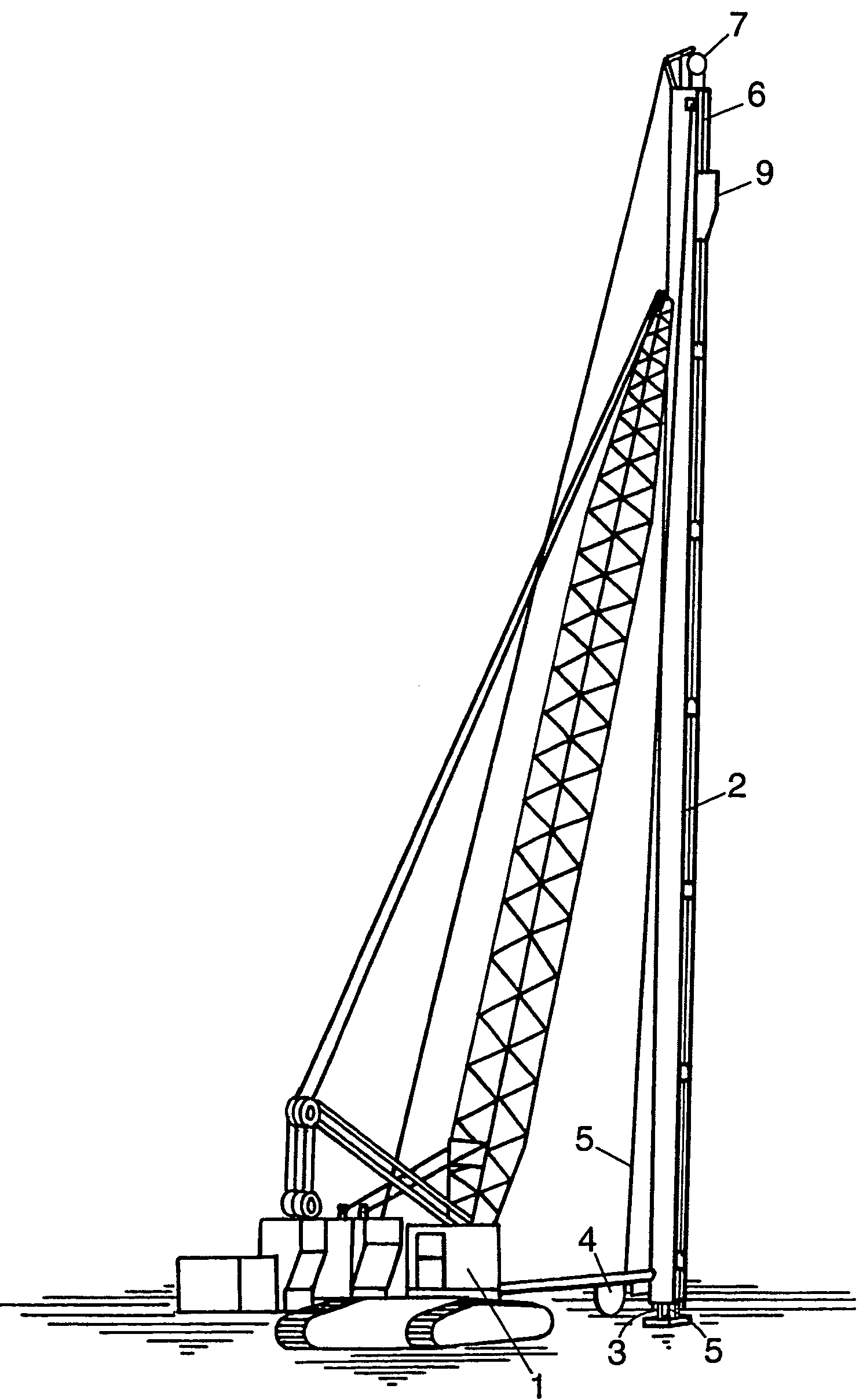
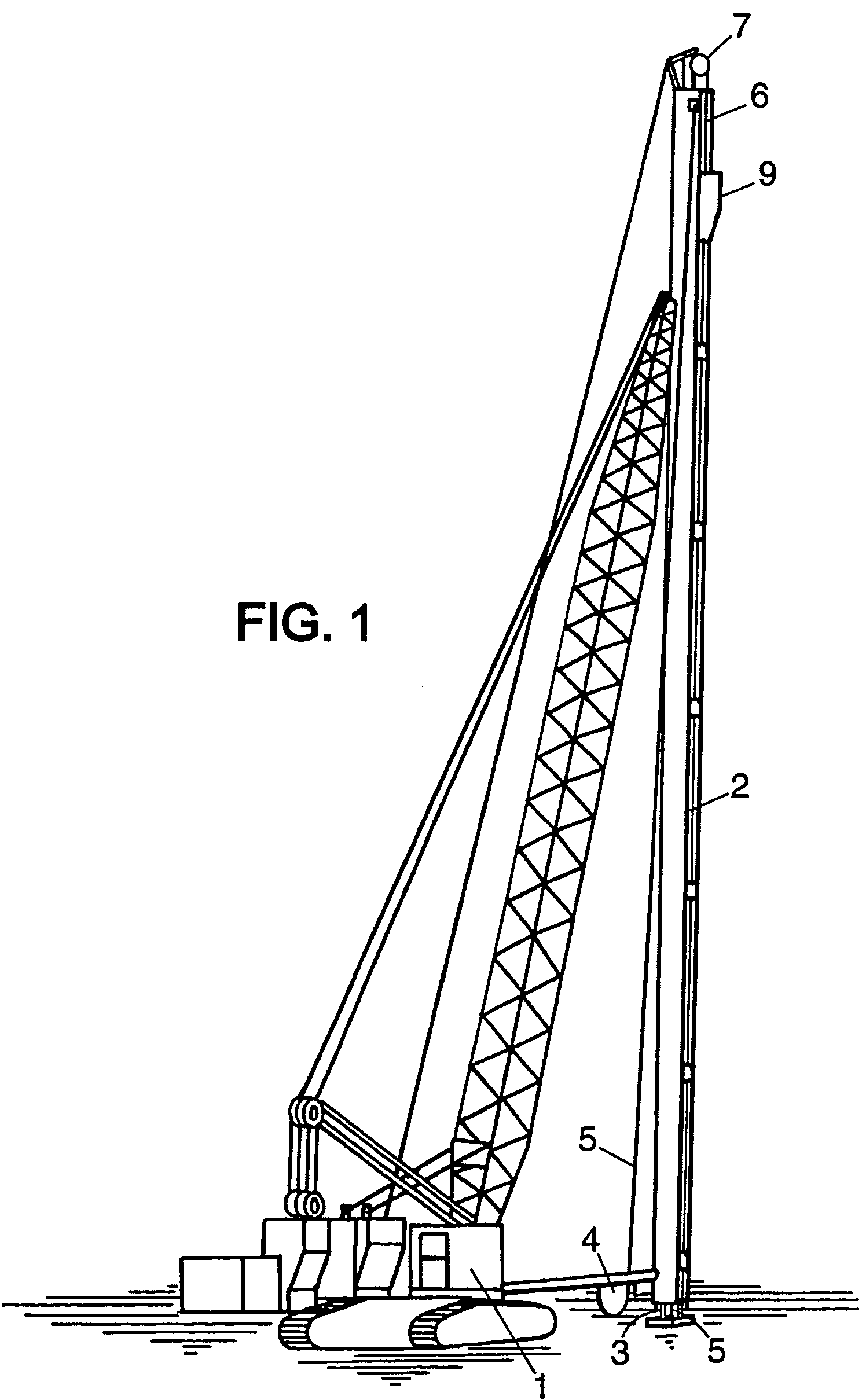
[0058]An embodiment of a device used to implement an example of a process according to the invention is shown in FIG. 1 and comprises: a frame formed by a hydraulic crane 1; a mast, column, shaft or guide 2; an inserting tube 3; supply means 4 for a drainage wick 5; and a drive member such as a cable 6. Guide 2 is arranged in a generally vertical position in operating conditions.

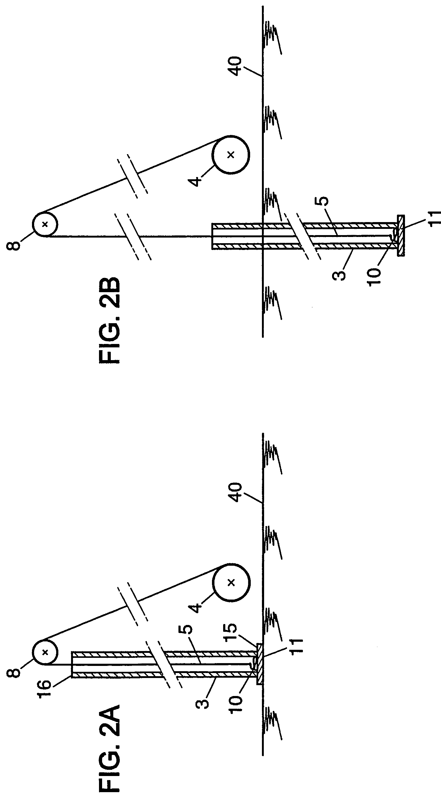
[0059]The guide 2 may typically comprise a hollow tube for example, which has been inserted or is insertable into the soil. Assuming that the guide 2 has been inserted into the soil, the wick inserting tube 3 may then be moved or directed through the guide or guide tube 2 to transfer the drainage wick 5 into the soil. That is, the inserting tube 3 is moved in a downward direction through the guide tube 2 by means of a loop of cable 6 having opposite ends attached to a fastening element attached to the tube 3. The closed loop of cable 6 fits over the reversing driven wheel 7 at the top end of crane 1 and an i...


PUM


Abstract

A method and device for inserting a drainage wick into the ground wherein the method includes the steps of:threading a drainage wick through an inserting tube;fixing a portion of a tie to the lower end of the drainage wick;fixing an anchorage component to another portion of said tie, where said tie is loose between the drainage wick lower end and the anchorage component when the anchorage component contacts the inserting tube lower end;driving a anchorage component, the drainage wick and the inserting tube downwardly into the ground;pulling up the inserting tube and the drainage wick, whereby said anchorage component is permitted to remain in the ground; andfurther pulling up the inserting tube whereby the anchorage component and the drainage wick are permitted to remain in the ground.

Description

BACKGROUND OF THE INVENTION[0001]The invention relates to a method of inserting a drainage wick into the ground and to a device for anchoring the drainage wick.[0002]Drainage wicks are commonly used for carrying out vertical draining in the ground in order to improve the strength of ground and generally consist of paper material in the form of strips or of a band-shaped plastic core enclosed in a suitable filter material.[0003]Such drainage wicks are widely used to consolidate soft compressible soils (such as clays and / or fine grained soils). Consolidation of a compressible soil occurs as pore water is squeezed from the soil matrix. The installation of vertical drains provides shortened drainage paths for the water to exit the soil and thus can reduce significantly the soil settlement time.[0004]In order to insert such a drainage wick in the ground, for example to a depth of 10 m up to 40 or 60 m, the drainage wick is threaded through an inserting tube or column after the tube is dr...

Claims


Application Information

Patent Timeline
Patent Type & Authority Patents(United States)
IPC IPC(8): E02B11/00
CPCE02D3/10
Inventor MORIZOT, JEAN-CLAUDEPEARLMAN, SETHTAUBE, MARTIN
Owner FREIXENET SA
Why Eureka
Try Eureka