Dual stage input lever transmission downshift system

Inactive Publication Date: 2009-10-29
COOK DAVID
View PDF15 Cites 26 Cited by
  • Summary
  • Abstract
  • Description
  • Claims
  • Application Information

AI Technical Summary

Benefits of technology

[0011]To partially release the paddle, the driver can just lessen the force he applies to the lever allowing it to return to the position where the spring force abruptly drops which is at the end of the first stage of travel where the clutch switch is still actuated and the clutch is still disengaged, but the downshift switch is now deactivated. The driver holds this lever position keeping the clutch disengaged with a reasonable amount of pressure at this point and can also move the paddle back and forth a small distance to insure he is at the spot between the stages without the clutch re-engaging.
[0012

Problems solved by technology

Attention and control complexity arise because the drivers have only two feet available to operate all three pedals.
When slowing a race car down, a driver will have to have one foot on the clutch to downshift the transmission and one on the brake to decelerate the car; there is then a measurable amount of time lost when the driver needs to move his foot form the brake pedal to the accelerator pedal to change from braking to accelerating.
Physical dimension issues arise because the three pedal system requires a certain width of space in the nose of the car and in an ope

Method used


Image

  • Dual stage input lever transmission downshift system
  • Dual stage input lever transmission downshift system
  • Dual stage input lever transmission downshift system

Examples


Embodiment Construction

[0028]In the following detailed description, certain specific terminology will be employed for the sake of clarity and a particular embodiment described in accordance with the requirements of 35 USC 112, but it is to be understood that the same is not intended to be limiting and should not be so construed inasmuch as the invention is capable of taking many forms and variations within the scope of the appended claims.

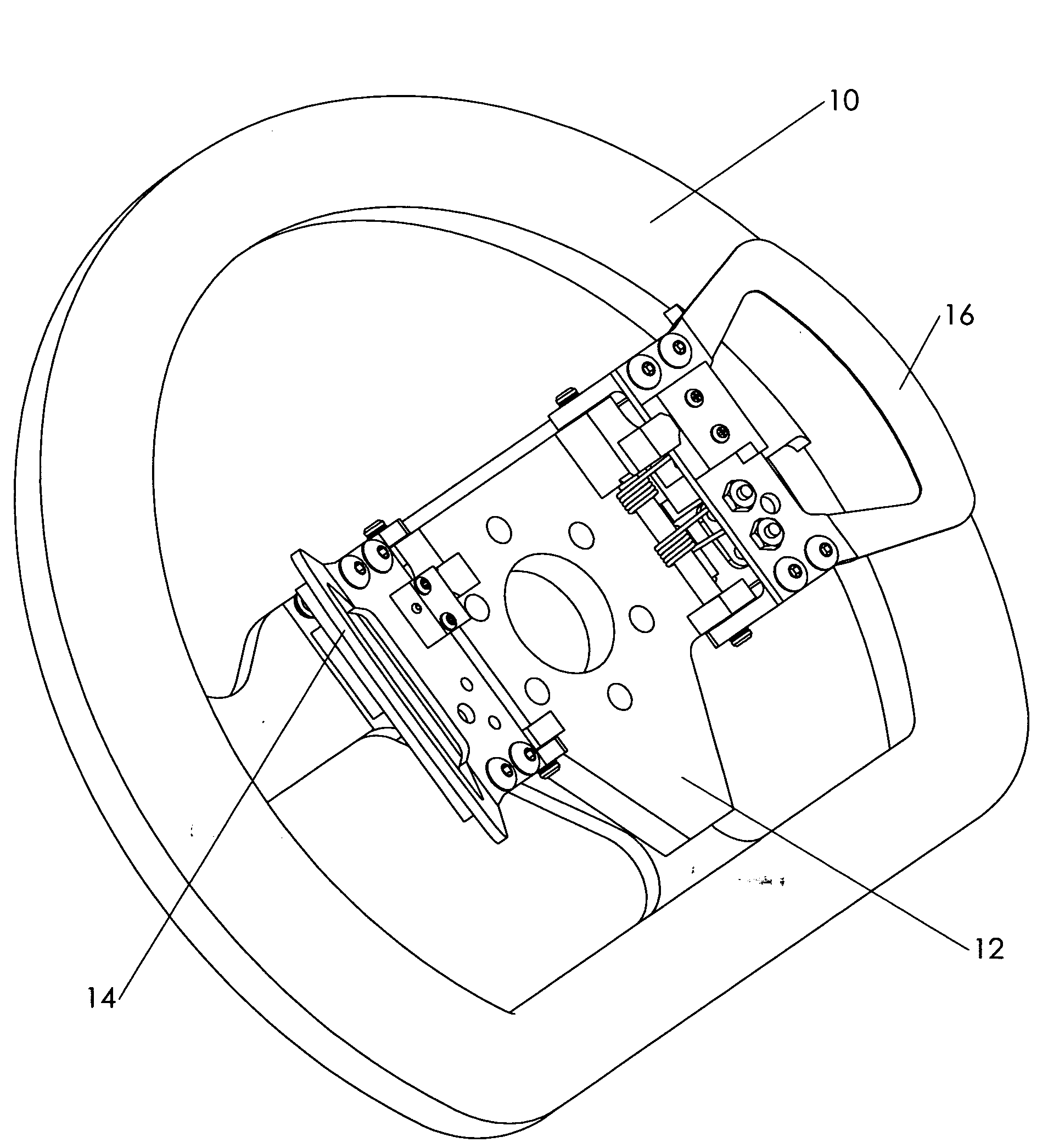
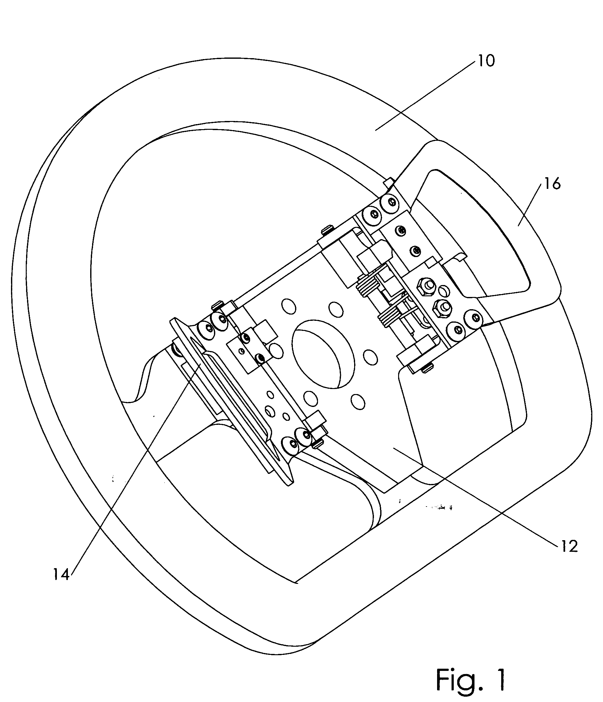
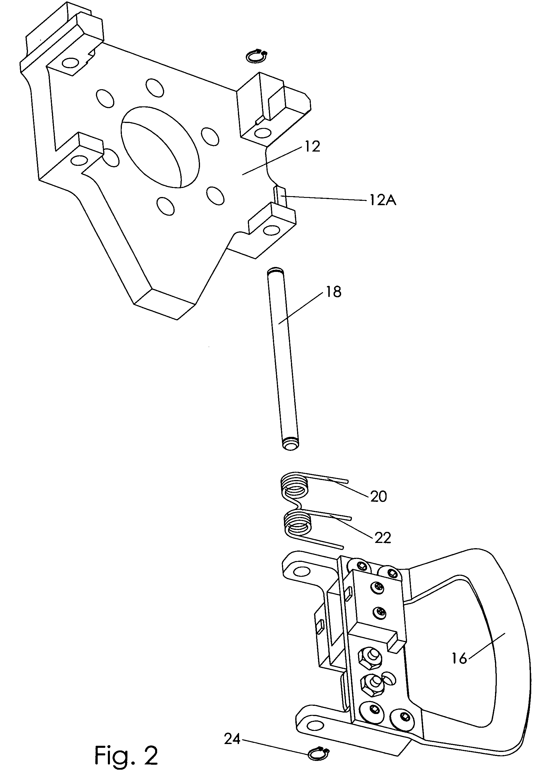
[0029]A preferred embodiment of the shift system is illustrated in FIGS. 1 through 3. The clutch / downshift paddle 16 and the upshift paddle 14 are mounted to the paddle assembly base 12 by pivot shafts 18 which are retained by pivot shaft retaining circlips 24. The entire paddle assembly is mounted to the back of a steering wheel 10 with the clutch / downshift paddle 16 on the left side as viewed by the driver. The downshift stage return spring 22 and the clutch stage return spring 20 are mounted to be concentric with and retained by the pivot shaft 18. Both springs apply ...


PUM


Abstract

A two stage clutch and shift actuation paddle assembly provides clutch disengagement through a first range of movement of a manually operated control lever or paddle and electronic shifting of a transmission upon movement through a second range. A return spring force generator causes a lower return force to be exerted on the generator paddle in a range of motion wherein the clutch is disengaged and a pronounced increased spring force to be exerted in advanced range of motion wherein the transmission shift actuation occurs.

Description

BACKGROUND OF THE INVENTION[0001]This invention relates to the shifting of sequential transmissions in motor vehicles, and relates specifically to a system that allows an operator to shift a sequential transmission by manipulating a control lever.DESCRIPTION OF THE PRIOR ART[0002]A sequential transmission as it applies to this invention is a transmission which is operated by a gear ratio selection lever that only moves about one axis. This operating lever has only one rest position, and when moved in one direction it selects gearing of a higher ratio and when moved in the opposite direction it selects gearing of a lower ratio. After the lever is moved all the way in either the upshift or downshift direction, the gear ratio changes. When the force that was required to move the lever is released, the lever returns to its static resting position. By comparison, non sequential transmission usually have a lever that moves about two axes as is found in the typical manual transmission auto...

Claims


Application Information

Patent Timeline
IPC IPC(8): B60K23/00B60K26/00B60W10/10
CPCB60K20/06B60K23/02Y10T74/20146Y10T477/6403B62D1/046
Inventor COOK, DAVID
Owner COOK DAVID
Why Eureka
Try Eureka