Recirculating microfluidic device and methods of use

a microfluidic and microfluidic technology, applied in the field of microfluidic devices, can solve the problems of limiting the cost of equipment, achieving the least expensive and perhaps the simplest signal amplification scheme, and achieving the most accurate detection of pathogenic organisms, reducing time, and increasing sensitivity

Inactive Publication Date: 2009-04-16
CORNELL RES FOUNDATION INC
View PDF5 Cites 26 Cited by
  • Summary
  • Abstract
  • Description
  • Claims
  • Application Information

AI Technical Summary

Benefits of technology

[0013]Microfluidics combined with a liposome signal amplification scheme, in accordance with the present invention, promises an inexpensive solution to the heightened need for technology that can rapidly and accurately detect pathogenic organisms in environmental, clinical, and food samples in the wake of recent threats of bioterrorism. Liposome technology has been used in analogous membrane detection systems with great success (Baeumner et al., Analytical Chemistry 74:1442-1448 (2002); Esch et al., Analytical Chemistry 73:3162-3167 (2001); and Rule et al., Clinical Chemistry 42:206-1209 (1996), which are hereby included by reference in their entirety). It has been reported that gains in sensitivity can be achieved by converting a liposome-based membrane detection assay for Cryptosporidium parvum to a microfluidic format (Esch et al., Analytical Chemistry 73:3162-3167 (2001); and Rule et al., Clinical Chemistry 42:206-1209 (1996); and Taton et al., Science 289:1756-1760 (2002), which are hereby incorporated by reference in its entirety) (see also Goral et al., “Electrochemical microfluidic biosensor for the detection of nucleic acid sequences,’Lab on a Chip 6(6):414-421 (2006); Zaytseva et al., “Microfluidic biosensor for the serotype-specific detection of dengue virus RNA,”Analytical Chemistry 77(23):7520-7527 (2005); and Zaytseva et al., “Development of a microfluidic biosensor module for pathogen detection,”Lab on a Chip 5(8):805-811 (2005), which are hereby incorporated by reference in their entirety).
[0014]The passive microfluidic mixer of the present invention is capable of establishing a recirculating flow inside mobile and open volumes from the nanoliter to the microliter range. Mixing in the device occurs not by generating transverse flows perpendicular to the length of the channel (see Stroock et al., Science 295:647-651 (2002), which is hereby incorporated by reference in its entirety), but instead by generating transverse flows parallel to the length of the channel, such that streamline segments at different lengths of the channel can be brought into contact with each other. It takes advantage of a fluid-exchange principle (described in U.S. Pat. No. 6,331,073 to Chung et al., which is hereby incorporated by reference in its entirety): the device provides order-changing functions to a microfluid, i.e., allowing sections of fluid separated by a length of the channel to interact directly. The device effectively “folds” the solution to permit streamlines that are normally linearly separated to come into contact. In one embodiment, the microfluidic device is a microfluidic mixer that is pressure driven in an open-end chamber using an attached syringe controlled by an external motor.
[0015]The present invention relating to the recirculating microfluidic mixer can find application in a variety of bioanalytical and chemical micro / nano systems, such as (but not limited to) microfluidic sensors, micro-Total Analysis Systems. For example, it can be used for the effective and rapid mixing of several solutions, it can be used to decrease the time needed for a nucleic acid sequence-based amplification (NASBA) reaction, or any catalytically derived reaction, any hybridization reaction, any binding reaction (e.g., RNA-DNA hybridization reactions using liposome and magnetic beads with immobilized DNA oligonucleotides).

Problems solved by technology

While molecular methods tend to be more sensitive, specific, and faster than culture based methods, they are also limited by expensive equipment requirements (Baeumner et al., Analytical Chemistry 74:1442-1448 (2002)).
The least expensive and perhaps the simplest signal amplification scheme has been achieved with liposomes.

Method used


Image

  • Recirculating microfluidic device and methods of use
  • Recirculating microfluidic device and methods of use
  • Recirculating microfluidic device and methods of use

Examples


example 1

Investigation of Liposome Lysis Using the Fluorescence Detection Approach

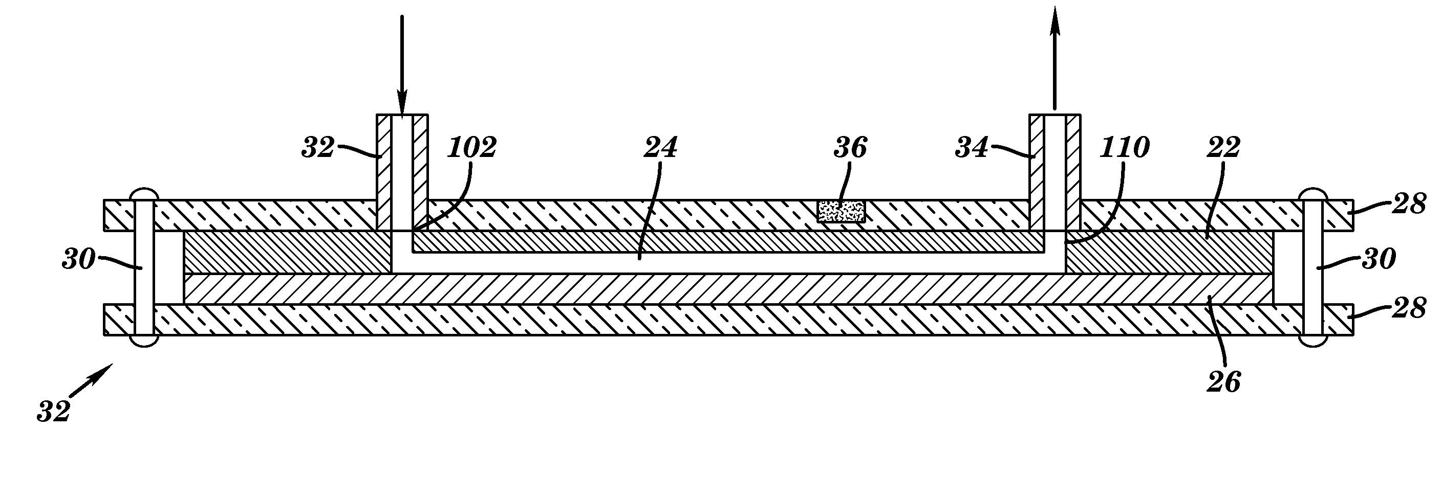
[0133]Through inlet 102 of the microfluidic device shown in FIG. 8 and described above, a sample mixture containing complexes of bead—target RNA—liposome is introduced. A mixture containing liposomes encapsulating sulforhodamine B, magnetic beads, target RNA, and a hybridization buffer (60% formamide, 6×SSC, 0.8% Ficoll type 400, 0.01% Triton X-100, 0.15M sucrose) was injected through inlet 102. Captured beads were washed from unbound liposomes by injecting a washing buffer (10% formamide, 3×SSC, 0.2% Ficoll type 400, 0.01% Triton X-100, 0.2M sucrose) into inlet 102. At this point, signals can be detected using the CCD camera connected to the fluorescence microscope. Exposure times were optimized (1 sec), and signals were analyzed using Image Pro Express software. Alternatively, in order to increase the signal to noise ratio by lysing liposomes and obtaining a significantly higher fluorescence signal due to the...

example 2

Optimization of RNA Detection in the Microfluidic Channels

[0134]A series of experiments was performed in order to optimize the detection of RNA in the microfluidic channels. These experiments were done without any liposome lysis and were monitored using the fluorescence microscope. The amount of liposomes (1.61 OD value for 1 / 100 dilution in PBS+ sucrose buffer, pH 7.0, osmolality 630 nmol / kg) with immobilized reporter probe (FIG. 17), beads with immobilized capture probe (FIG. 18) and washing buffer (up to 14 μL) were optimized with respect to signal to noise ratio. Therefore, the limit of detection was obtained for the analysis of Dengue virus RNA. The amount of reporter probe was 0.013 mol % from the total amount of lipids. The biotinylated capture probe was immobilized on the surface of the beads (Dynabeads MyOne Streptavin) following the manufacturer protocol. 1 mg of the beads binds approximately 3,000 pmoles of free biotin.

example 3

Electrochemical Analysis of Liposome Capture in the Microfluidic Device

[0135]To test the IDUA response in microfluidic system, as shown in FIG. 10, different volumes (20 nL-100 nL) of 10 μM potassium hexaferrocyanide / potassium hexaferricyanide solution were injected at flow rate of 1 μl / min into inlet 108, while buffer solution was introduced at flow rate of 1 μl / min through inlet 102. The typical result of the IDUA response in the single continuous run is provided in FIG. 20.

[0136]These results demonstrated that indeed the system based on the IDUA is capable of a fast response to the electrochemical composition changes inside the channel. The delay time between injection and the maximum signal reached was about 5-7 sec. In all the experiments the IDUA itself demonstrates a good reproducibility and the ability to function for prolonged periods of time without mechanical cleaning.

[0137]The typical results of RNA analysis by means of electrochemical detection is present in FIG. 21. In...


PUM

PropertyMeasurementUnit
bias potentialaaaaaaaaaa
flow rateaaaaaaaaaa
lengthaaaaaaaaaa

Abstract

The present invention relates to a microfluidic test device for detecting or quantifying an analyte in a test sample. The device includes a non-absorbent substrate having at least one microchannel imbedded in the substrate, a non-specific capture device, and one or more stationary mixing structures extending into the at least one microchannel. The present invention also relates to relates to various methods of using the microfluidic test device to detect or quantify an analyte in a test sample. The present invention also relates to a microfluidic device that includes a non-absorbent substrate having at least one microchannel imbedded in the substrate and one or more stationary mixing structures extending into the at least one microchannel.

Description

[0001]This application claims the benefit of U.S. Provisional Patent Application Ser. No. 60 / 689,720, filed Jun. 10, 2005, which is hereby incorporated by reference in its entirety.[0002]The subject matter of this application was made with support from the United States Government under CSRESS Contract No. NYC-123-404 and National Institutes of Health Grant No. 1 R01 HD37109-01A1. The U.S. Government may have certain rights.FIELD OF THE INVENTION[0003]The present invention is directed to a microfluidic device and to methods of using it.BACKGROUND OF THE INVENTION[0004]Molecular biology based technologies, such as the polymerase chain reaction (PCR), for detection of pathogenic microorganisms are slowly replacing culture based detection methods (Kow et al., Journal of Medical Entomology 378(4):475-479 (2001); Laue et al., Journal of Clinical Microbiology 37(8):2543-2547 (1999); and Illen et al., Journal of Virol. Methods 41(2):135-146 (1993)). While molecular methods tend to be more ...

Claims


Application Information

Patent Timeline
Patent Type & Authority Applications(United States)
IPC IPC(8): C12Q1/68C12M1/34
CPCG01N27/3277
Inventor BAEUMNER, ANTJE J.NICHOLS, KEVINNUGEN, SAM R.ZAYTSEVA, NATALYA V.GORAL, VASILIY N.KWAKYE, SYLVIA DOKUA SAKYIAMA
Owner CORNELL RES FOUNDATION INC
Why Eureka
Try Eureka