Reconfigurable and replaceable RFID antenna network

a technology of radio frequency identification and antenna network, which is applied in the direction of burglar alarm mechanical actuation, burglar alarm by hand-portable article removal, instruments, etc., can solve the problems of user inability to modify the configuration of the rfid antennae to account for changing products, the reader antennae is fixed in place, and the contents of a volatile memory are lost, etc., to achieve the effect of convenient replacement and great functionality

Inactive Publication Date: 2006-06-15
BLACK & DECKER INC
View PDF22 Cites 26 Cited by
  • Summary
  • Abstract
  • Description
  • Claims
  • Application Information

AI Technical Summary

Benefits of technology

[0011] A system that incorporates replaceable antennae makes it possible for the user to reconfigure a shelf to a multitude of configurations and thereby add greater functionality to the reader (which may be a reader / writer). At the same time, damaged antennae can be easily replaced without assistance from a specially skilled technician. All of this is achieved through various embodiments of the present inventive concept.
[0012] Since an antenna of the present invention is easily removed, it can easily be replaced with an identical or different format antenna. Combining this concept with a standard, inexpensive rail interface allows for the antenna to be placed in numerous locations. The concept need not be combined with a rail interface, and can instead be combined with magnets, dual lock, velcro, and other means for fixing the antenna in place, and thus provide for easy removal.
[0013] A single design results in an inexpensive solution due to the economy of scale concept. Also, since the end user has the capability to modify the shelf to his or her own requirements, this solution is more attractive than the prior art, because it offers greater functionality.
[0015] Preferably, each of the signaling units can be connected to the RFID reader or writer using an antenna configuration apparatus. This antenna configuration apparatus includes a plurality of pieces that are communicatively connected to the RFID reader or writer, and also includes a base for supporting the plurality of pieces. The plurality of pieces are dimensioned so as to attach to the signaling units. Two or more of those pieces are designed so that they each can be removably attached to a particular signaling unit that will have different orientations depending upon which of the two or more pieces is used for the attachment. In other words, the signaling units will have different orientations with respect to each other, and so the present invention enables a user to easily arrange the signaling units to form a wide variety of geometries.

Problems solved by technology

Since the operating voltage comes from the RF field, the contents of a volatile memory are lost when the field is not present.
The main disadvantage of the arrangement disclosed in FIG. 3 and FIG. 4 is that the reader antennae are fixed in place and are not easily replaceable or reconfigurable.
The user cannot modify the RFID antennae configuration to account for changing product sizes and / or product tag location.
This type of functionality forces the production of multiple design configurations that is both expensive and time-consuming, and may not even be useful to the end user.
Another shortcoming of the prior art design is in the difficulty of replacing a damaged antenna.
A skilled technician would be responsible for disassembly and replacement of the unit, which will be time-consuming and costly.

Method used


Image

  • Reconfigurable and replaceable RFID antenna network
  • Reconfigurable and replaceable RFID antenna network
  • Reconfigurable and replaceable RFID antenna network

Examples


Embodiment Construction

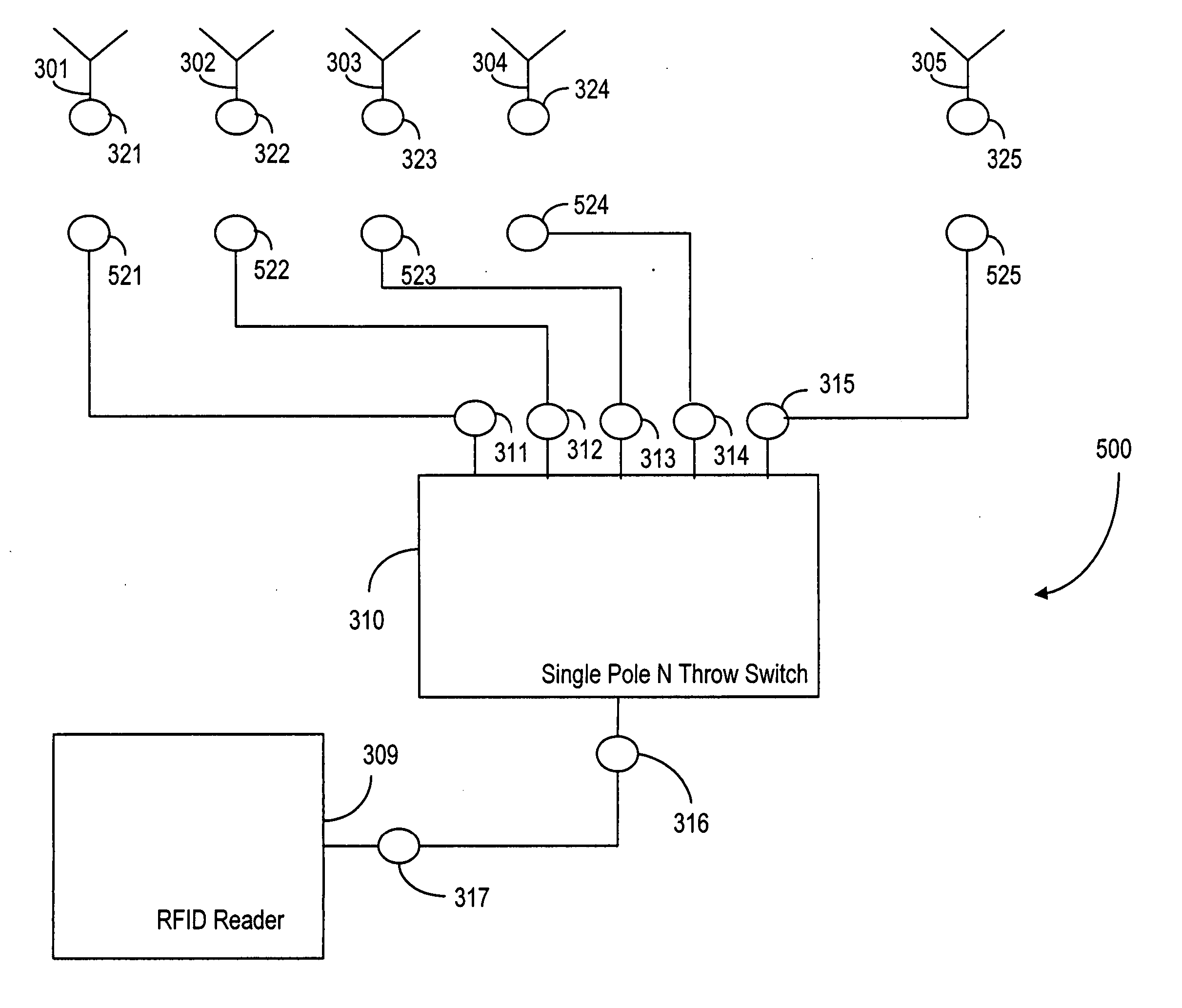
[0025] The present invention provides a system that tracks and locates RFID tags. The preferred embodiment of the system includes a reader unit, a switch matrix comprising single pole multiple throw switches, reconfigurable and easily replaceable antennae, and a controller (computer) that communicates with the reader and controls the state of the switch matrix.

[0026] This preferred embodiment of the system also includes a shelf or multiple shelves such as those used in a cabinet, bookshelf, or electronic media shelving. The shelf contains products with RFID tags attached, and the RFID tags will be identified and located by the proposed system. The operating frequency of the preferred embodiment is 13.56 MHz, but the concept may also be applied to other frequency bands, such as UHF. Such a system may be used, for example, in medical cabinets to track such items as stents and pharmaceuticals. Other applications may include the tracking of library books, DVDs and other electronic medi...


PUM


Abstract

An RFID reader system for tracking and locating RFID tags is described, along with an antenna suitable for use in this system, and an antenna configuration apparatus for use in this system. The system offers an antenna configuration that is cost-effective and easily reconfigurable, in which antennas with integral tuning components can be moved or replaced with antennas of a similar or different format. An end user is therefore able to easily reconfigure his or her platform in the field, in order to account for different products or different product orientations. Specific orientations of the reader antennae will furthermore increase system functionality by permitting multiple tag locations on the product.

Description

FIELD OF THE INVENTION [0001] The present invention relates to Radio Frequency Identification (RFID) technology, and more particularly to RFID technology used in conjunction with shelves in stores and other environments. BACKGROUND OF THE INVENTION [0002] RFID technology has become well-known over the past few decades, and its wireless potentialities continue to be expanded and exploited. Implementing an RFID device has certain basic features. The simplest RFID device is the TAG. The tag is typically a completely passive device in that it contains no internal power source; a passive tag derives its operating power from the RF field used to interrogate the tag. A passive RFID Tag 100 is shown as a block diagram in FIG. 1. However, it should be noted that tags can be active also. [0003] The tag's only link to the outside world is normally the antenna 110, shown in FIG. 1 with connections LA and LB. When the antenna picks up an RF field of the proper amplitude and frequency, an operati...

Claims


Application Information

Patent Timeline
Patent Type & Authority Applications(United States)
IPC IPC(8): G08B13/14
CPCG06K7/0008G06K7/10178G06K7/10336
Inventor MARINO, RONALD A.
Owner BLACK & DECKER INC
Why Eureka
Try Eureka