Internal mixing atomizing spray nozzle assembly

a technology of spray nozzles and atomizers, applied in the direction of spray nozzles, combustion types, lighting and heating apparatus, etc., can solve the problems of increasing capital and operating costs, and achieve the effect of effective atomizing liquid sprays

Inactive Publication Date: 2006-05-02
SPRAYING SYST
View PDF8 Cites 53 Cited by
  • Summary
  • Abstract
  • Description
  • Claims
  • Application Information

AI Technical Summary

Benefits of technology

[0003]It is an object of the present invention to provide a spray nozzle assembly which can operate at lower air pressures for effectively atomizing liquid sprays for use in gas scrubbing or other applications in which the discharging spray must have a fine liquid particle distribution.

Problems solved by technology

A problem with such prior spraying nozzles is that relatively high pressurized air is required to achieve adequate liquid particle break-down and atomization, which increases capital and operating costs.

Method used


Image

  • Internal mixing atomizing spray nozzle assembly
  • Internal mixing atomizing spray nozzle assembly
  • Internal mixing atomizing spray nozzle assembly

Examples


Embodiment Construction

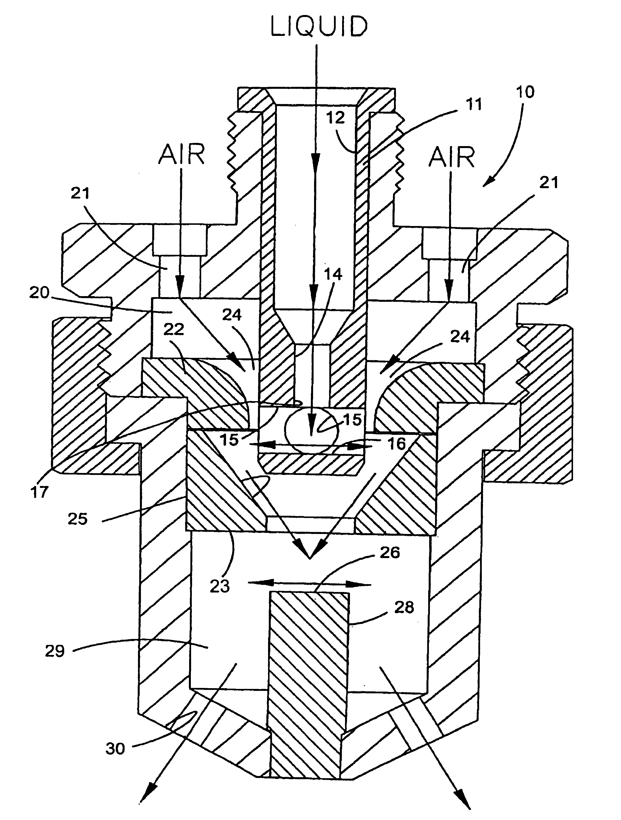
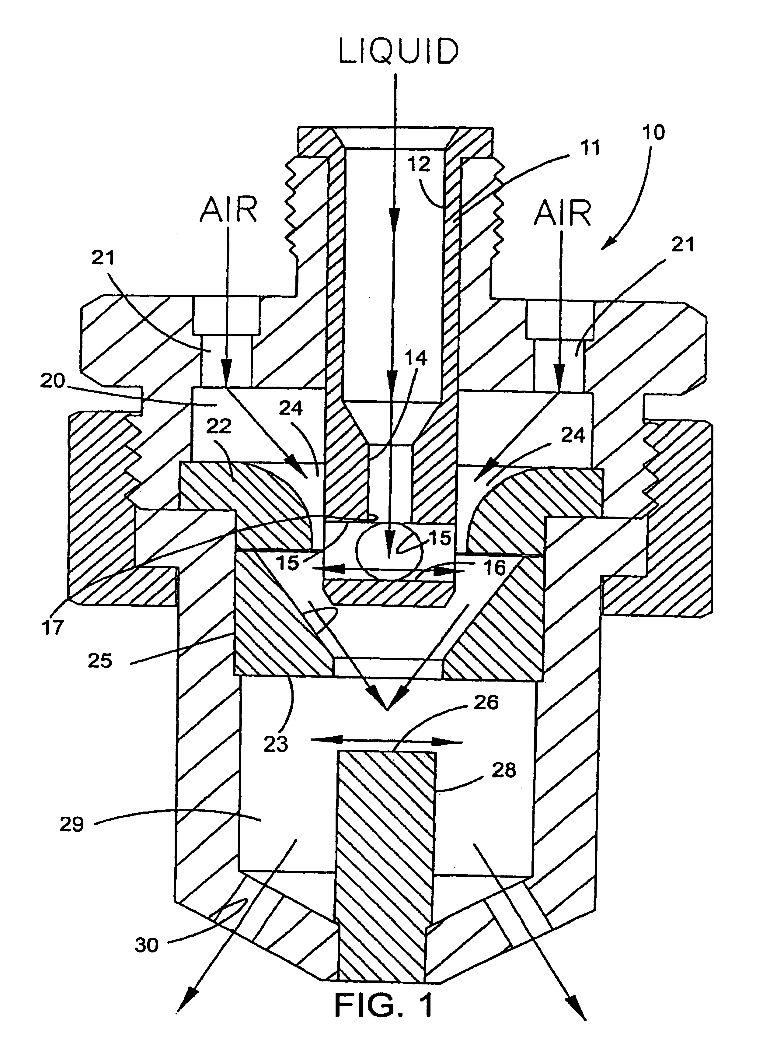
[0007]Referring now more particularly to FIG. 1 of the drawings, there is shown a multi-stage spray nozzle assembly 10 in accordance with the invention. The spray nozzle assembly 10 is an improvement upon, however similar in certain respects, to the multi-stage air atomizing spray nozzle assembly shown in U.S. Pat. No. 5,732,885, assigned to the same assignee as the present application, the disclosure of which is incorporated herein by reference. In the illustrated embodiment, the nozzle includes a multi-part body that includes a main body portion with an upwardly extending and externally threaded neck defining an inlet that is adapted to attach to a line for delivering pressurized fluid to the nozzle. A nozzle tip is positioned below the main body portion and is removably attached thereto by a coupling nut. The one or more discharge orifices of the nozzle are formed in the nozzle tip as described in greater detail below.

[0008]The body of the spray nozzle assembly 10 includes a liqu...


PUM


Abstract

A nozzle for atomizing and spraying liquid is provided. The nozzle includes a longitudinal liquid flow passageway that terminates in a liquid orifice for directing a stream of liquid along a predetermined axis. A plurality of intersecting, transverse passageways extend perpendicular to and intersect the predetermined axis. Each of the transverse passageways terminates at either end in an outlet. The transverse passageways define a first impingement surface downstream of the liquid orifice for breaking up a stream of liquid impinging thereon into a laterally spreading dispersion which disperses through the transverse passageways. An air annulus is arranged in surrounding relation to the outlets of the transverse passageways and oriented to discharge air in a downstream direction so as to strike the fluid dispersed through the outlets of the transverse passageways. An expansion chamber is arranged downstream of the transverse passageways and air annulus. The expansion chamber communicates with a nozzle discharge orifice.

Description

FIELD OF THE INVENTION[0001]The present invention relates generally to spray nozzle assemblies, and more particularly, to spray nozzle assemblies in which liquid is atomized by pressurized air prior to discharge from the nozzle.BACKGROUND OF THE INVENTION[0002]Spray nozzle assemblies are known which utilize pressurized air for breaking down liquid into relatively small particle sizes. Such nozzle assemblies have particular utility in gas scrubbing applications, where ammonia or urea is sprayed into a discharging stream of combustion gases for removing nitric oxide or other combustion by-products. A problem with such prior spraying nozzles is that relatively high pressurized air is required to achieve adequate liquid particle break-down and atomization, which increases capital and operating costs.OBJECTS AND SUMMARY OF THE INVENTION[0003]It is an object of the present invention to provide a spray nozzle assembly which can operate at lower air pressures for effectively atomizing liqui...

Claims


Application Information

Patent Timeline
Patent Type & Authority Patents(United States)
IPC IPC(8): B05B7/06B05B1/34A62C5/00B05B1/14B05B1/26B05B7/04B05B7/08F23J7/00F23J15/00
CPCB05B7/0466F23J15/003F23J7/00B05B7/0475B05B1/14B05B1/265B05B7/0892
Inventor HUFFMAN, DAVID C.
Owner SPRAYING SYST
Why Eureka
Try Eureka