Locking structure for a clamp

a technology of locking structure and clamp, which is applied in the direction of insulated cables, candle holders, lightening support devices, etc., can solve the problems of affecting the stability of the clamp, the inability of the locking wings to prevent the rotation of the clamp b>1/b>, and the interference of other components and elements in the vicinity, so as to facilitate and smooth couple the entire inner periphery, prevent damage, and strengthen the support pin

Inactive Publication Date: 2006-05-02
SUMITOMO WIRING SYST LTD
View PDF23 Cites 63 Cited by
  • Summary
  • Abstract
  • Description
  • Claims
  • Application Information

AI Technical Summary

Benefits of technology

[0011]In the construction of the present invention, when the clamp is locked and fixed with the through hole of a counterpart member, the through hole engages with the base and the coupling stepped section can come in contact with the entire periphery of the inner peripheral surface of the through hole. Therefore, the base completely blocks the through hole, and thereby prevents dust and water from passing through the through hole. Moreover, a clamp having a base in the above construction is formed using a mold with segments which are put together along a direction which intersects with the axis of a support pin. With this design, the clamp can be molded without gaps being created at locations on a base plate facing the locking wings which would appear when a conventional clamp is molded using a mold which is separated across a plane including the axis of a support pin.
[0012]Additionally, it is preferred that a pair of guide portions which extend in directions intersecting the locking wings are integrally formed on the support pin and that sloped guide surfaces are formed from the tip of the support pin to the coupling stepped section on the outer surfaces of the guide pieces. With this design, when the clamp is inserted into a through hole, the sloped guide surfaces of the guide portions as well as the outer surfaces of the locking wings come in contact with and slide over an opening peripheral section of the through hole. Therefore, the clamp can be guided to the central position within the through hole and thereby, the locking step section can comfortably and smoothly couple the entire inner periphery of the through hole.
[0013]Further, if reinforcement ribs are formed between the guide portions and the base, the support pin can be made stronger and thereby, can be prevented from being damaged by an external force to the clamp.
[0014]The through hole may be of an elongated shape and the coupling stepped section of the base may be designed to match the entire periphery of the inner periphery surface of the elongated shape. With this design, the coupling stepped section of the base comes in contact with the entire periphery of the inner peripheral surface of the through hole and the through hole has an elongated shape, both of which work together to prevent the clamp from rotating with respect to the through hole. Therefore, a component which the clamp locks and fixes to a counterpart member is locked and fixed to the through hole while its rotational movements are also restricted. Therefore, the component to be fixed would not interfere with other components and can be precisely positioned at a desired position and maintained there.
[0015]Additionally, a component to be fixed is an electrical connection box and the counterpart member is an automotive body panel. The clamp may be formed integrally on an outer surface of the electrical connection box while the electrical connection box may be fixed on the automotive body panel through the clamp. According to the above construction, when the electrical connection box is fixed on the automotive body panel through the clamp, coupling between a coupling stepped section formed on a base of the clamp and a through hole with an elongated shape on the automotive body panel would not allow the electrical connection box to rotate and can fix it with a desired orientation. Therefore, when the electrical connection box is fixed by fastening bolts on other locations of the box, alignments will not be lost as bolts are inserted into bolt holes and the work operability to fix the box can be improved.

Problems solved by technology

Gaps appear between clamp 1 and through hole P. Therefore, these gaps allow foreign objects and water to flow in, and it is difficult to apply clamp 1 to locations where dust control or water proofing is necessary.
Moreover, even if through hole P is an elongated hole, there is an issue in that clamp 1 easily yields to a rotational force applied on clamp 1 and rotates.
Therefore, locking wings 4 can not prevent clamp 1 from rotating.
Thus, the component to be fixed does not remain at a fixed location and there is a concern in that it may interfere with other components and elements in the vicinity.
However, there is the problem that the component may move if the clamp 1 rotates, making it difficult to fix the component.
Hence, when an excess rotational force is applied to clamp 1′, locking wings 4′ still deform against elastic resistance to close, thereby making it difficult to provide secure locking against rotation.
Therefore, gaps can not be eliminated and it is difficult to provide for perfect protection against dust and water.

Method used


Image

  • Locking structure for a clamp
  • Locking structure for a clamp
  • Locking structure for a clamp

Examples


Embodiment Construction

[0030]The particulars shown herein are by way of example and for purposes of illustrative discussion of the embodiments of the present invention only and are presented in the cause of providing what is believed to be the most useful and readily understood description of the principles and conceptual aspects of the present invention. In this regard, no attempt is made to show structural details of the present invention in more detail than is necessary for the fundamental understanding of the present invention, the description is taken with the drawings making apparent to those skilled in the art how the forms of the present invention may be embodied in practice.

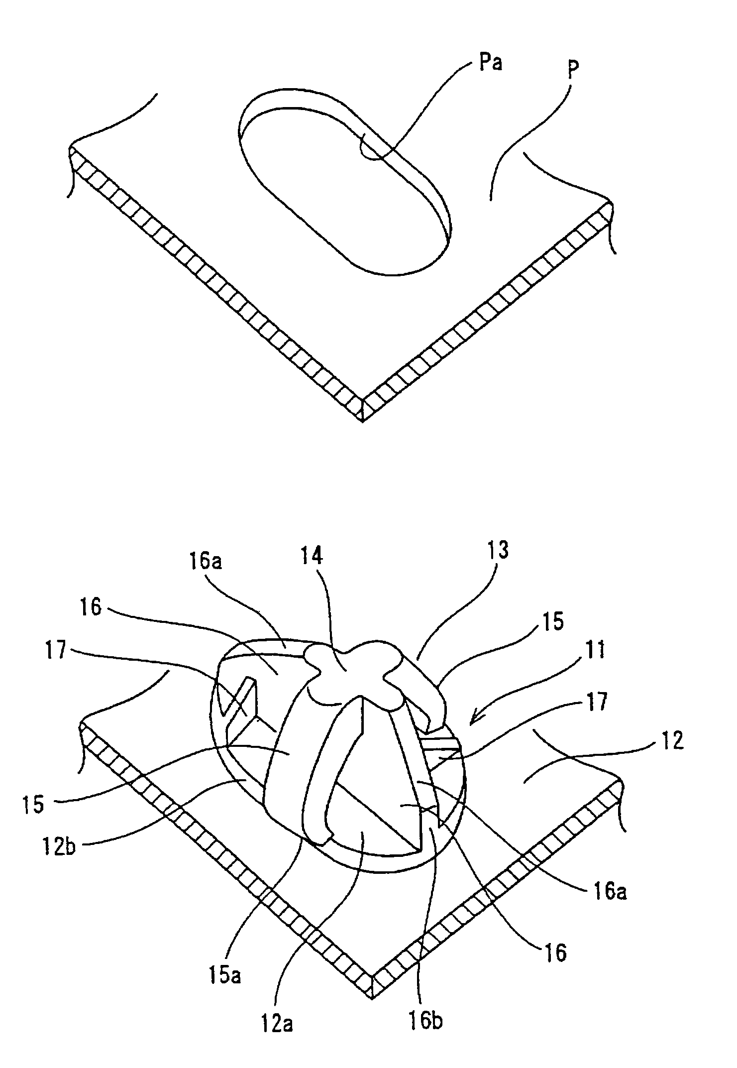
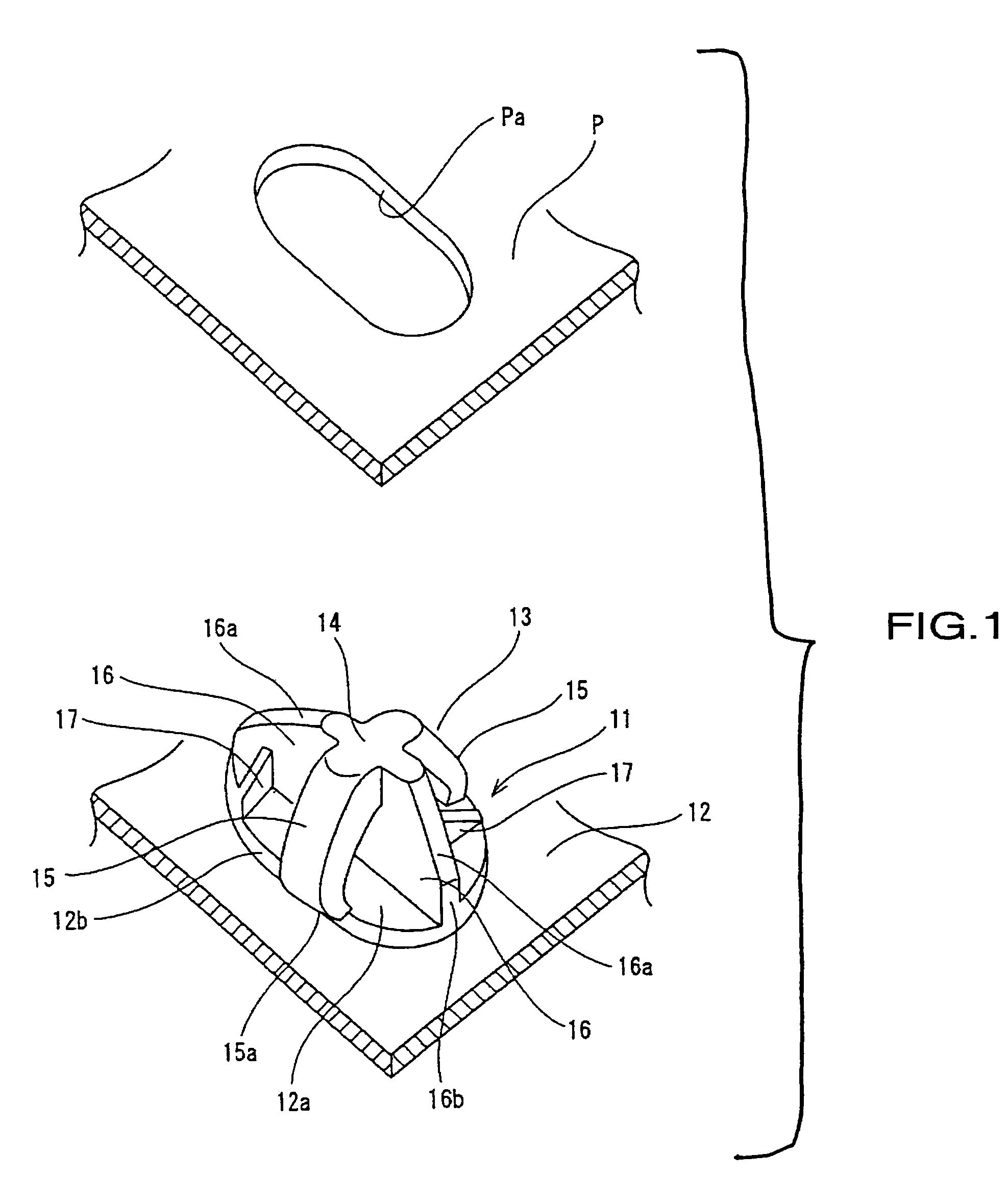
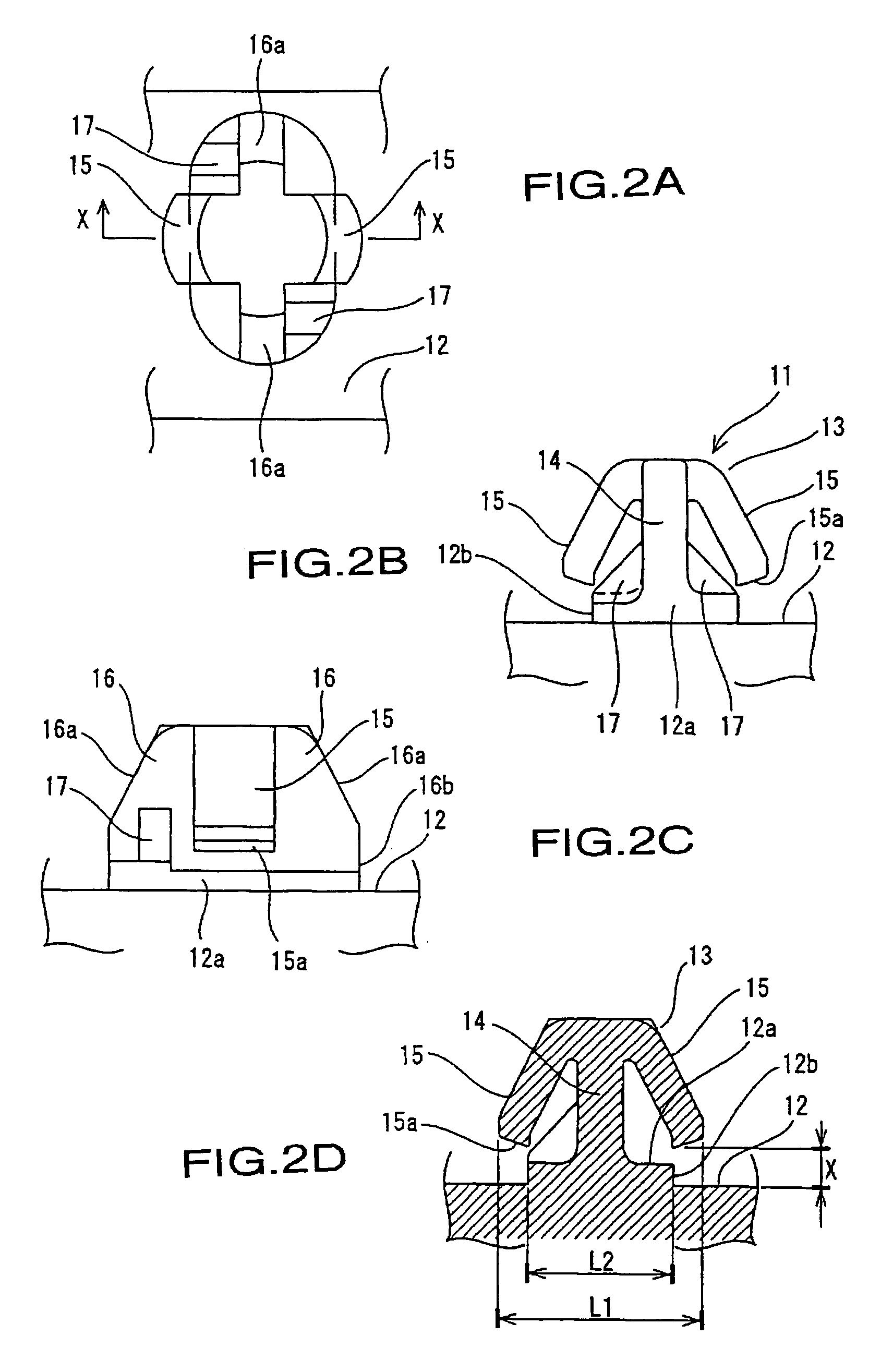
[0031]Below, the first example of the present invention is explained with reference to the figures. As illustrated in FIGS. 1–3, clamp 11 may be constructed of any suitable material such as, for example, synthetic resin. The clamp includes base plate section 12 which may be formed integrally and in one piece with a component t...


PUM

PropertyMeasurementUnit
locking structureaaaaaaaaaa
elongated shapeaaaaaaaaaa
distanceaaaaaaaaaa

Abstract

In a locking structure for a clamp, the clamp is formed with a projecting component to be fixed to a counterpart member through a through hole of the counterpart member via locking wings. A base plate section is equipped with a coupling step section which can engage the through hole and contact the entire inner peripheral surface of the through hole Pa. The locking structure can prevent the clamp from rotating by making the through hole of the counterpart member in an elongated shape while making the base in an elliptical shape.

Description

BACKGROUND OF THE INVENTION[0001]1. Field of the Invention[0002]The present invention relates to a locking structure for a clamp, and more particularly to a locking structure for a clamp which enables a component to be fixed to a counterpart member such as an automotive body panel to be securely locked and fixed through a through hole in the counterpart member.[0003]2. Description of the Background Information[0004]Conventionally, a clamp 1 is generally used as a member to fix elements to portions of an automotive body, as shown in FIGS. 5A and 5B. This clamp is equipped with a pair of locking wings 4 formed to extend rearwardly from the tip section of support pin 3 which projects from base plate section 2. The outer surface sections of the tips of locking wings 4 are equipped with locking stepped sections 4a to be locked through a through hole Pa formed on automotive body panel P.[0005]To lock the clamp 1 to automotive body panel P, first, the tip of support pin 3 is inserted force...

Claims


Application Information

Patent Timeline
Patent Type & Authority Patents(United States)
IPC IPC(8): F16B15/00H01B7/00B60R16/02F16B5/00F16B5/02F16B5/06F16B19/00F16B21/08H02G3/30
CPCF16B5/0642F16B5/0657F16B21/088F16B5/0664Y10T24/309
Inventor KAWAGUCHI, KIYOFUMIKATAYAMA, TOMOYOSHI
Owner SUMITOMO WIRING SYST LTD
Why Eureka
Try Eureka