Motorcycle rear frame mounting system

a rear frame and mounting system technology, applied in the direction of bumpers, vehicular safety arrangments, bicycle equipment, etc., can solve the problems of compromising the look and resale value of the motorcycle, compromising the sleekness of the motorcycle design, and the components are generally not easily removable from the support brackets of the motorcycl

Inactive Publication Date: 2006-05-02
POLARIS IND INC
View PDF12 Cites 59 Cited by
  • Summary
  • Abstract
  • Description
  • Claims
  • Application Information

AI Technical Summary

Benefits of technology

[0005]According to a first aspect of the invention, there is provided a motorcycle. The motorcycle comprises a frame, a front wheel, a rear wheel, a rear fender, and one or more components. The front wheel is operatively coupled to a front portion of the frame, and the rear wheel is operatively coupled to a lower rear portion of the frame. The rear fender is directly coupled to an upper rear portion of the frame, and the one or more components are directly coupled to the upper rear portion of the frame.
[0006]According to a second aspect of the invention, there is provided a motorcycle. The motorcycle comprises a frame and a rear fender. The frame has a front and rear portion, in which the rear portion includes an upper portion and a lower portion. The upper rear portion includes one or more rear frame rails, with each rail having a plurality of holes located therein. The rear fender is directly coupled to the upper rear portion of the frame and includes a plurality of bores located therein. Each of the plurality of bores is configured to align with one of the plurality of holes in one of the rear frame rails.
[0007]According to a third aspect of the invention, there is provided a method of mounting a rear fender to a motorcycle frame while keeping the mounting hardware concealed but readily accessible. The method involves removing a first rear fender and any mounting hardware from an upper rear portion of the motorcycle frame. Two holes are drilled into the upper rear portion of the motorcycle frame. Two bores are drilled into a second rear fender to align with the two holes in the upper rear portion of the motorcycle frame. The second rear fender is secured to the upper rear portion of the motorcycle frame, and at least one cover adapted to conceal one or more of the bores in the second rear fender is provided. At least one aperture is drilled into the at least one cover to align with one of the bores in the second rear fender and one of the one of the holes in the upper rear portion of the motorcycle frame. The at least one cover is secured to the upper rear portion of the motorcycle frame.

Problems solved by technology

While it may be perfectly reasonable to weld or bolt additional supporting brackets to the frame for support for these components, the modification may very well compromise the motorcycle's look and resale value as well.
Further, if the components are removable, once they are removed, one may be left with support brackets or mounting holes not being utilized, which would likely compromise the sleekness of the motorcycle design.
Another problem in regard to the support brackets and the components attached thereon is that, even if the components are removable, the components are generally not easily removable from the support brackets of the motorcycle.

Method used


Image

  • Motorcycle rear frame mounting system
  • Motorcycle rear frame mounting system
  • Motorcycle rear frame mounting system

Examples


Embodiment Construction

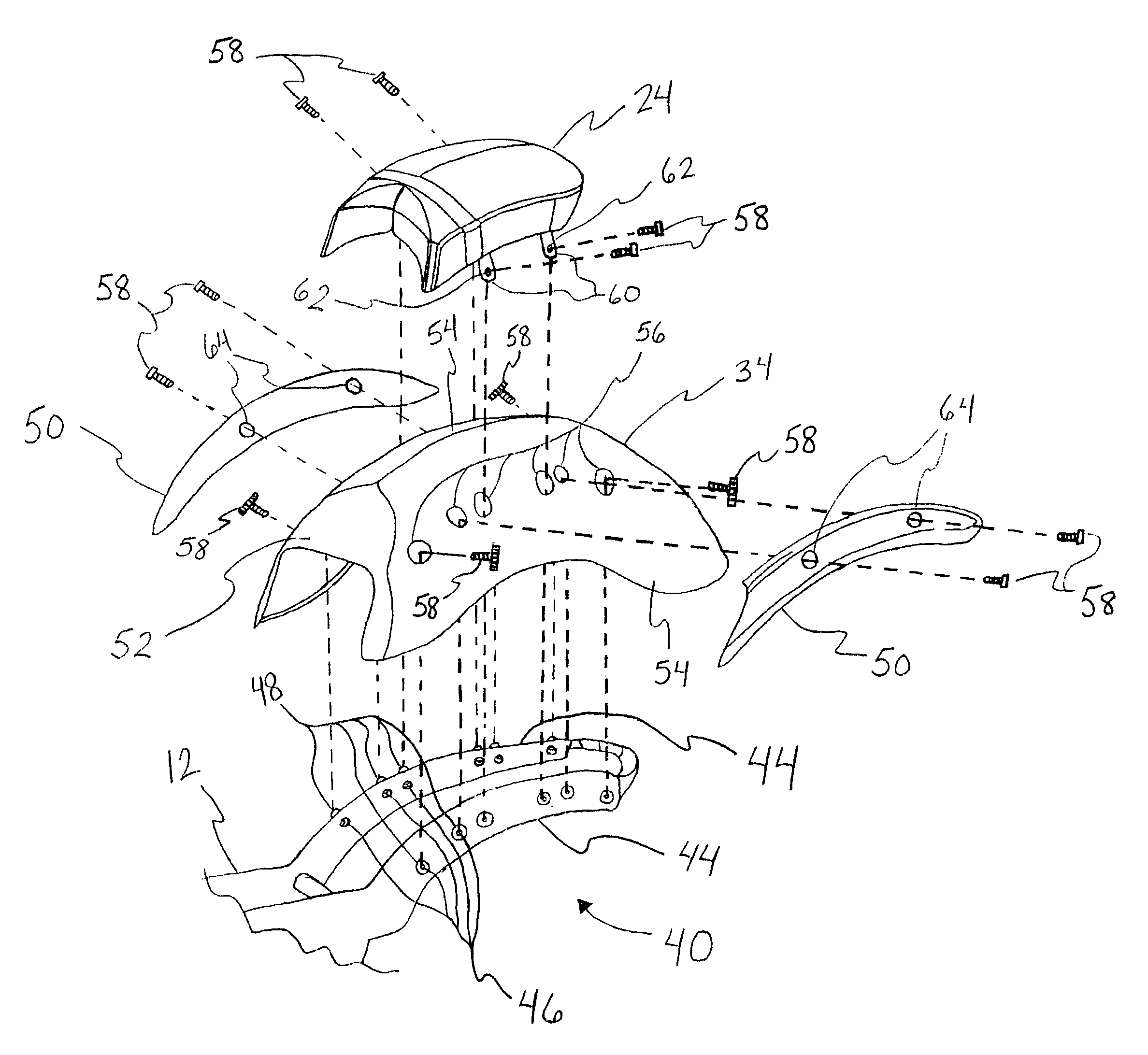
[0015]The following detailed description is to be read with reference to the drawings, in which like elements in different figures have like reference numerals. The drawings, which are not necessarily to scale, depict selected embodiments, but are not intended to limit the scope of the invention. It will be understood that many of the specific details of the vehicle incorporating the system illustrated in the drawings could be changed or modified by one of ordinary skill in the art without departing significantly from the spirit of the invention. The mounting system of the invention is designed for use on vehicles such as motorcycles, however, it may be applied to other vehicles such as mopeds, scooters, bicycles, all-terrain vehicles, and the like.

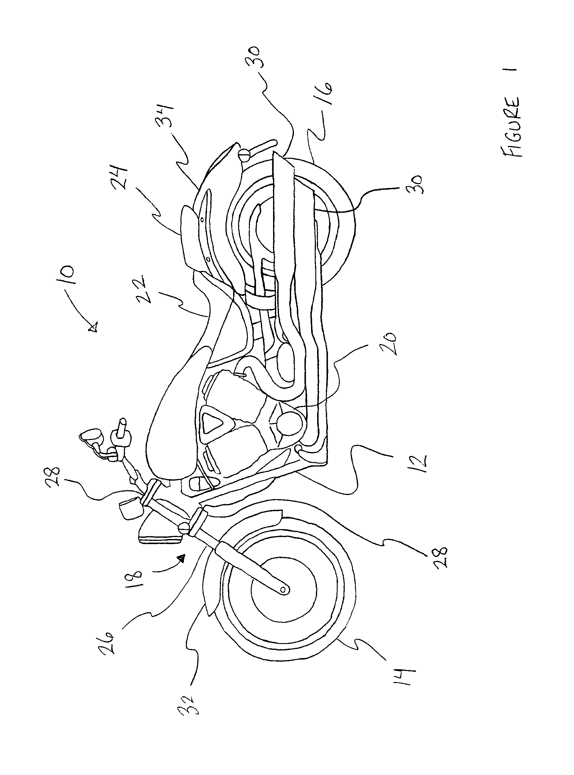
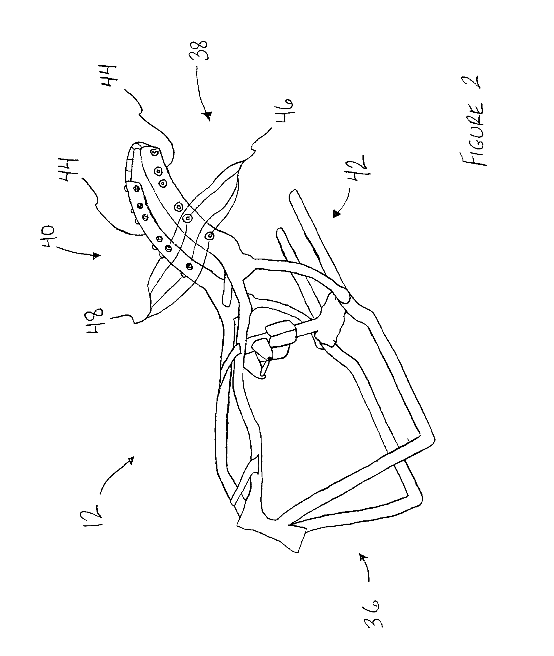
[0016]FIG. 1 illustrates a side view of a motorcycle 10 in accordance with certain embodiments of the invention. The motorcycle 10 includes a frame 12, a front wheel 14, a rear wheel 16, a steering fork 18, an engine 20, a driver seat 22,...


PUM


Abstract

The invention provides a method and apparatus utilized to mount a motorcycle fender, as well as one or more components, directly to an upper rear portion of a motorcycle frame. The upper rear portion of the frame includes one or more rear frame rails, each having a plurality of holes defined therein. These holes are further used in securing the fender and the one or more components.

Description

[0001]This application is a continuation of U.S. application Ser. No. 10 / 612,279, filed Jul. 1, 2003, now abandoned.TECHNICAL FIELD[0002]The invention relates to a system for mounting items onto a vehicle, and in particular, for mounting a fender and one or more components onto a frame of a motorcycle.BACKGROUND OF THE INVENTION[0003]There are a number of existing ways to support a motorcycle rear fender. One well-known technique involves attaching struts to a rear axle of the motorcycle, including the well-known “sissy” bar, for supporting the fender. Other well-known techniques involve attaching supports to a portion of a motorcycle other than the axle. Generally, these other well-know techniques comprise either welding a support directly to the frame or drilling holes into the frame and then bolting the support directly to the frame. Although welding and bolting to the frame will provide strong support for the fender, the strength of such fastening systems is not the only conside...

Claims


Application Information

Patent Timeline
Patent Type & Authority Patents(United States)
IPC IPC(8): B62D61/02B62J7/04
CPCB62J15/02B62K19/40B62K19/30B62J1/12B62J1/14B62J7/04B62J9/23B62J9/24B62J25/06B62K11/04
Inventor BAUER, KATHY JGRAY, GARY C.WOLF, JEFFREY P.HOEVE, JASON W.B.SONG, MICHAEL M.
Owner POLARIS IND INC
Why Eureka
Try Eureka