
Coaxial cable termination system

a termination system and coaxial cable technology, applied in the direction of cable terminations, electric cable installations, cable junctions, etc., can solve the problems of difficult electrical connection to the wire section and shield connection features, high risk of connection failure, and high resistance variation, so as to ensure the connection is reliable and free of strain, the effect of high reproducibility

Inactive Publication Date: 2006-05-02
DELPHI TECH INC
View PDF4 Cites 12 Cited by
  • Summary
  • Abstract
  • Description
  • Claims
  • Application Information

AI Technical Summary

Benefits of technology

[0011]The coaxial cable termination system according to the present invention may be used to connect an end of a coaxial cable to a circuit board, wherein the die casting provides a reliable strain-free interface with the printed circuit board, and wherein the interface so provided is simply provided, with high reproducibility and with superior performance, as compared to that known in the prior art.

Problems solved by technology

Several drawbacks of using a crimp terminal for connecting a coaxial cable end to a circuit board, include: portions of the crimp terminal protruding in relation to the circuit board, creating radiated interference issues and RF coupling to the board's opposite side; core location on the circuit board is not reproducibly precise nor robust, thereby introducing impedance variation and risking connection failure; making the electrical connections to the wire section and shield connection features is difficult; and, crimping of the shield can have inconsistent RF performance with regard to the individual crimps of a number of made crimps.

Method used


Image

  • Coaxial cable termination system
  • Coaxial cable termination system
  • Coaxial cable termination system

Examples


Embodiment Construction

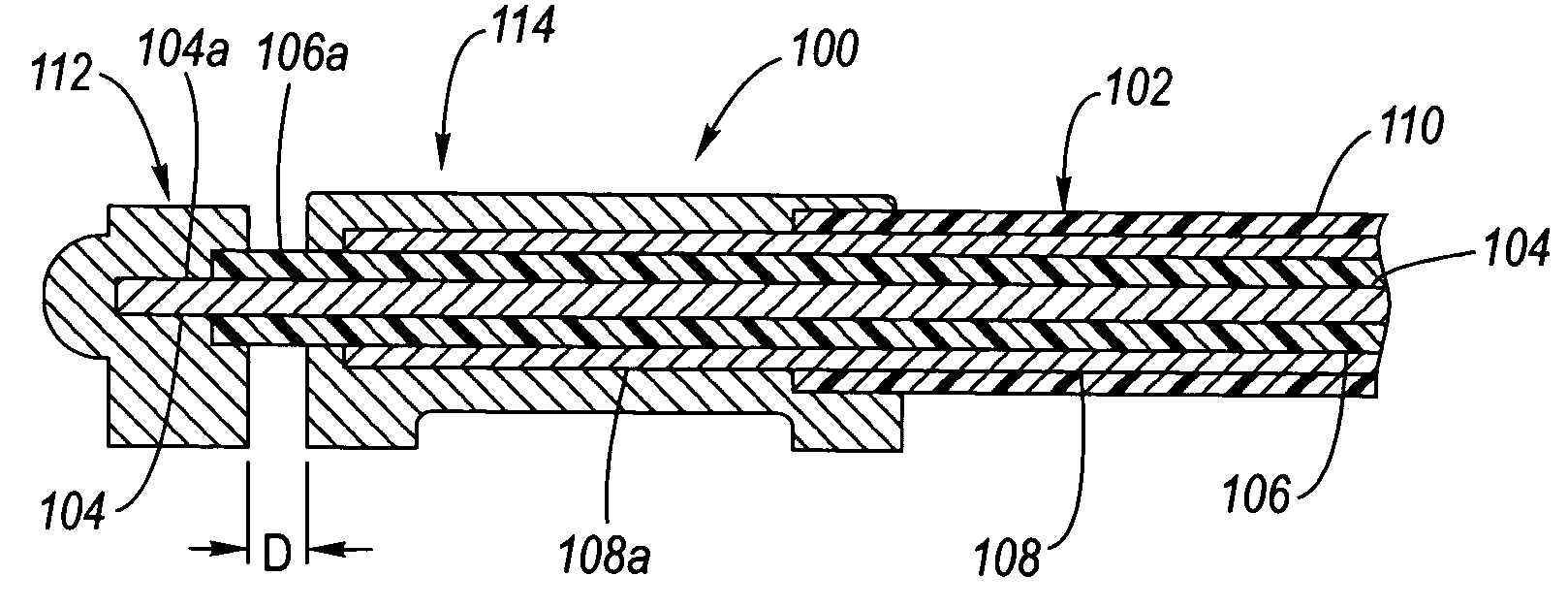
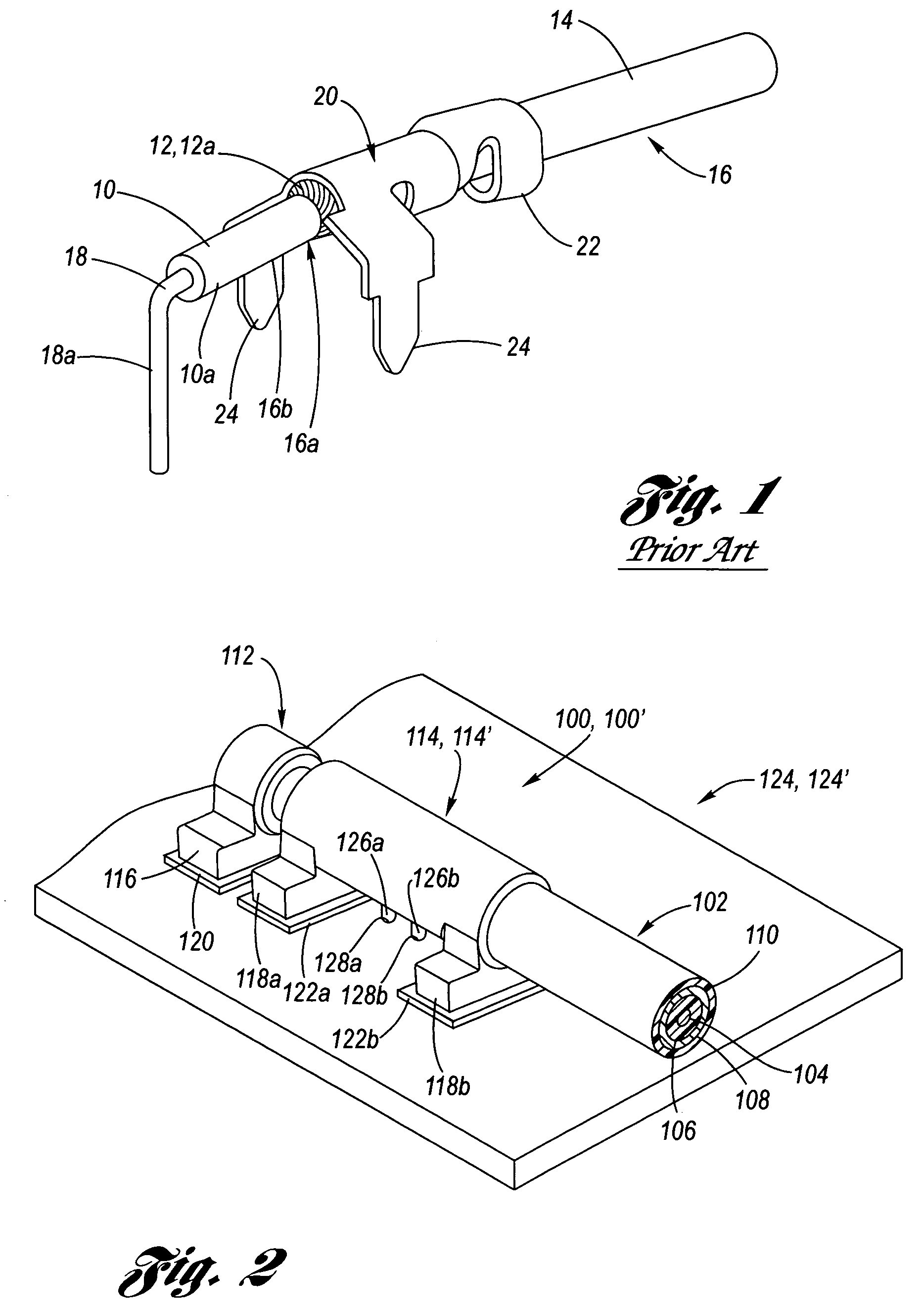
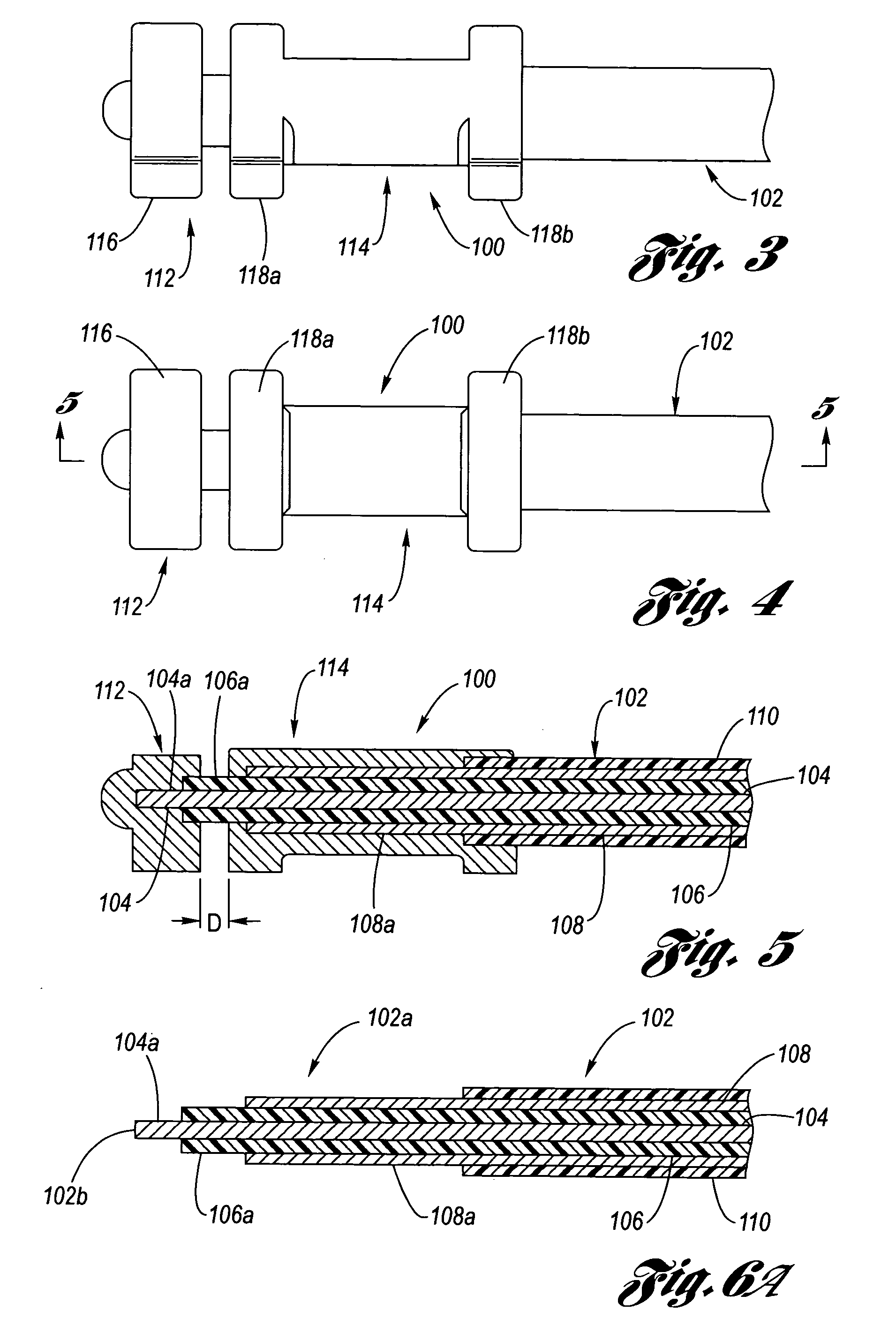
[0023]Referring now to the Drawing, FIGS. 2 through 6C depict various views of the coaxial cable termination system 100 according to the present invention, wherein the coaxial cable termination system is interfaced with a coaxial cable 102 having a conventional construction, as recounted hereinabove, of an electrically conductive core 104, an inner dielectric 106, an electrically conductive shield 108 and a jacket 110.

[0024]The coaxial cable termination system 100 includes a core body 112 electrically and mechanically connected with the core (inner conductor) 104 of a coaxial cable 102 (shown best at FIG. 5), and further includes a shield body 114 electrically and mechanically connected to the shield (outer conductor) 108 of the coaxial cable. Each of the core and shield bodies 112, 114 has respective attachment features 116, 118a, 118b which are configured as may be appropriate for a particular application, such as for example connecting to respective electrical connection pads 120...


PUM


Abstract

A coaxial cable termination system for providing a reliable electrical connection of an end of a coaxial cable to an electrical device. An electrically conductive core body is cast over the core of the coaxial cable, and an electrically conductive shield body is cast over the shield of the coaxial cable, wherein the core and shield bodies are electrically and mechanically connected to the coaxial cable, yet the core and shield bodies mutually have direct current electrical isolation with respect to each other. Each of the core and shield bodies has respective attachment features for a particular application, such as for example connecting to a circuit board.

Description

TECHNICAL FIELD[0001]The present invention relates to termination structures used to connect a coaxial cable to a circuit boardBACKGROUND OF THE INVENTION[0002]Coaxial cables have an inner electrical conductor, referred to herein simply as a “core,” an outer electrical conductor, referred to herein simply as a “shield” which is concentrically disposed around the core, an inner dielectric disposed between the core and the shield, and a protective outer covering, referred to simply herein as the “jacket.” Coaxial cables are used widely in the electrical arts, for example to send radio frequency (RF) from one electrical component to another. The shield provides the dual function of guiding the RF energy within the coaxial cable without allowing its escape to the outside, while preventing external RF energy from entering.[0003]By way of exemplification of a coaxial cable, the core and shield together form a conduit for the transmission of RF energy which travels through the dielectric, ...

Claims


Application Information

Patent Timeline
Patent Type & Authority Patents(United States)
IPC IPC(8): H02G15/08H01R9/05H01R43/24
CPCH01R43/24H01R9/0515
Inventor DAUGHERTY, JAMES D.ESENWEIN, FREDERICK DONALDGLADD, JOSEPH HOWARDKETTERER, WILLIAM CSPISAK, ANDREW MICHAEL
Owner DELPHI TECH INC
Learn More