Pointing device and cursor for use in intelligent computing environments

a technology of intelligent computing and cursor, which is applied in computing, instruments, electric digital data processing, etc., can solve the problems of prohibitively expensive and complex installation, and the acquisition of the geometric model of the room and its devices requires a further calibration phase,

Inactive Publication Date: 2006-05-02
MICROSOFT TECH LICENSING LLC
View PDF8 Cites 98 Cited by
  • Summary
  • Abstract
  • Description
  • Claims
  • Application Information

AI Technical Summary

Benefits of technology

[0017]The XWand system determines which device the user is pointing at by combining the orientation and 3-D position of the XWand with a 3-D model of the room and the devices within it. Orientation of the XWand is determined as explained above from the onboard sensors, while XWand position is determined with stereo computer vision. The 3-D model of the room and devices is entered into the system by pointing with the XWand itself in a special training mode. With the orientation, position and model of the room, it is easy to determine which if any object in the world model the XWand is pointing at. Audio feedback is provided to indicate to the user that the object is known to the system and can be controlled by the XWand, but in general little feedback is necessary since the pointing is absolute in nature.
[0018]The WorldCursor improves upon the XWand system by not requiring an external position sensing technology. There are a number of drawbacks to using the external computer vision system. First, the system involves installing multiple cameras in the room. Part of the installation requires a rather precise calibration of the cameras against the geometry of the room. Secondly, the acquisition of the geometric model of the room and its devices requires a further calibration phase. Thirdly, computer vision techniques rely on having a clear line of sight to the device. Although this can be alleviated somewhat by installing more cameras, this approach can be prohibitively expensive and complex to install. Finally, installation of cameras inevitably raises privacy objections. The combination of the WorldCursor with the XWand eliminates the need for the external camera setup.
[0026]However, if the approximate 3D geometry of the space is known or generated as described above, then there is also a technique to compute the precise 3D position of the pointing device (assuming it is unknown to the system) by exploiting the above mentioned clutching operation. In this way a more precise correspondence can be maintained as explained above. If the user is clutching so that the pointing device points at the laser spot, each of these clutching operations provide information that can be related mathematically to the 3D position of the pointing device. After a few such clutching operations, it is possible to compute the 3D position of the device. The advantage in doing so is that no more clutching operations are necessary to maintain pointing device-WorldCursor correspondence, so long as the actual position of the pointing device does not change dramatically. It is noted that this online calibration requires no more clutching operations than the system which does not exploit the approximate room geometry. Further in the long run it requires fewer clutching operations if the user does not move about the room often.

Problems solved by technology

This migration away from the desktop and “into the walls” presents several challenges for user interface design.
Typically, such devices are limited to one transmission scheme, such as IR or RF, and so can control only electronic components operating on that scheme.
This could add considerably to the cost of a “single UI-controlled” environment.
There are a number of drawbacks to using the external computer vision system.
First, the system involves installing multiple cameras in the room.
Secondly, the acquisition of the geometric model of the room and its devices requires a further calibration phase.
Thirdly, computer vision techniques rely on having a clear line of sight to the device.
Although this can be alleviated somewhat by installing more cameras, this approach can be prohibitively expensive and complex to install.
Finally, installation of cameras inevitably raises privacy objections.
However, this will not be the usual case because the WorldCursor will typically be mounted on the ceiling of the space.

Method used


Image

  • Pointing device and cursor for use in intelligent computing environments
  • Pointing device and cursor for use in intelligent computing environments
  • Pointing device and cursor for use in intelligent computing environments

Examples


Embodiment Construction

[0037]In the following description of the preferred embodiments of the present invention, reference is made to the accompanying drawings which form a part hereof, and in which is shown by way of illustration specific embodiments in which the invention may be practiced. It is understood that other embodiments may be utilized and structural changes may be made without departing from the scope of the present invention.

1.0 The Computing Environment

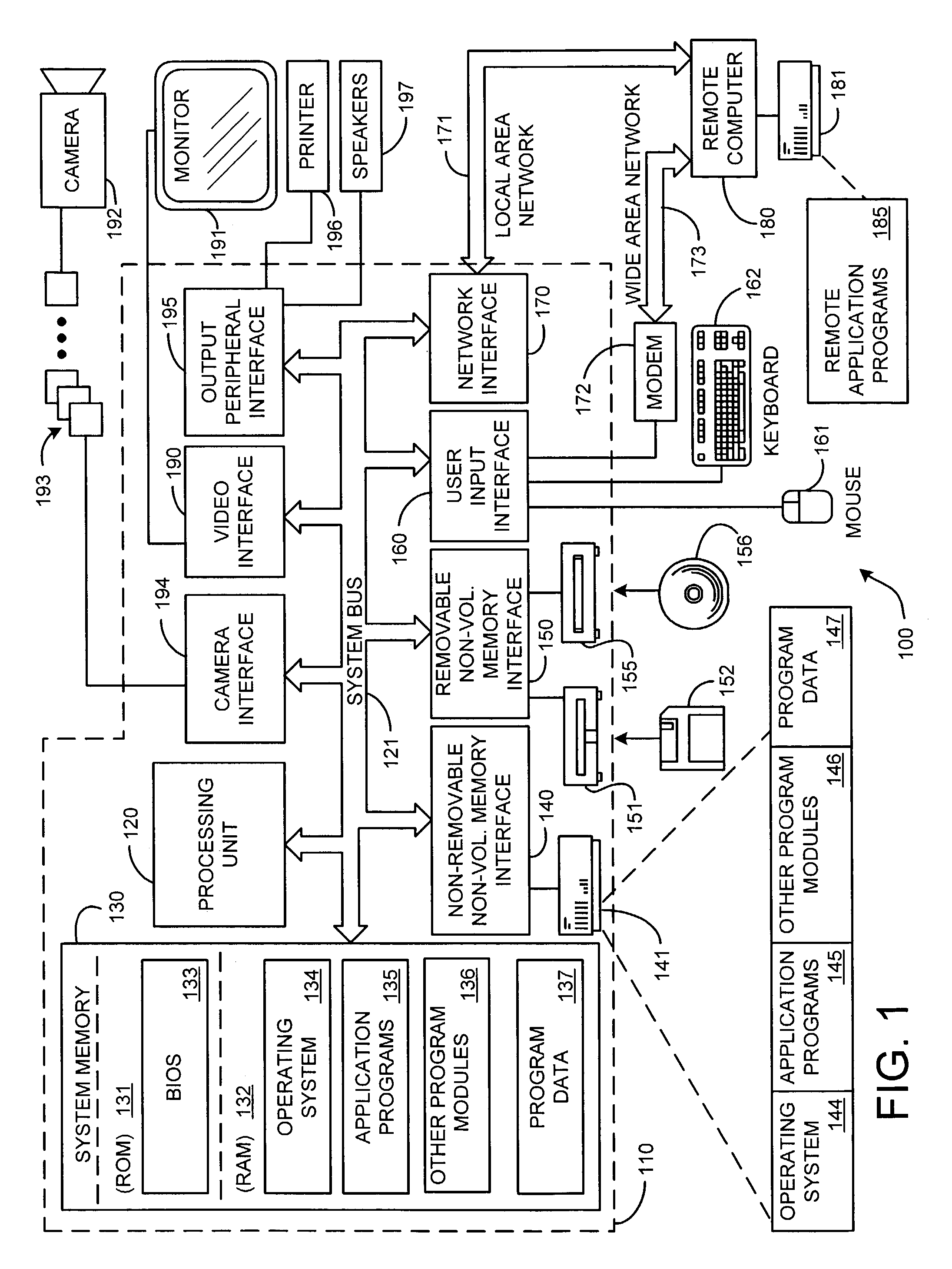
[0038]Before providing a description of the preferred embodiments of the present invention, a brief, general description of a suitable computing environment in which the invention may be implemented will be described. FIG. 1 illustrates an example of a suitable computing system environment 100. The computing system environment 100 is only one example of a suitable computing environment and is not intended to suggest any limitation as to the scope of use or functionality of the invention. Neither should the computing environment 100 be interpre...


PUM


Abstract

A system and process for directing a laser beam within a space is presented. The system includes a pointing device which periodically outputs orientation data indicative of the direction it is pointing and a cursor device which projects a laser beam. The orientation data is used to compute the direction the pointing device is pointing in terms of yaw and pitch angles. The laser beam is directed to locations in the space relative to the amount of movement of the pointing device. In an absolute mode, the pointed device and the laser beam of the cursor device are pointed at the same location in the space, whereas in a relative mode, the pointing device does not point at the same location as the laser beam. The position of the laser can be used to select a variety of hardware devices known to be in a room for future control actions.

Description

BACKGROUND[0001]1. Technical Field[0002]The invention is related to cursor devices, and more particularly to a system and process for directing a laser beam within a space to act as a cursor in an intelligent computing environment.[0003]2. Background Art[0004]Ubiquitous (i.e., intelligent) computing promises to blur the boundaries between traditional desktop computing and the everyday physical world. A popular vision of tomorrow's computing pushes computational abilities into everyday objects, each participating in a complex and powerful integrated intelligent environment. Tomorrow's home and office environments, for example, may include a variety of small and large networked displays and smart controllable devices. For instance, the modern living room typically features a television, amplifier, DVD player, lights, computers, and so on. In the near future, these devices will become more inter-connected, more numerous and more specialized as part of an increasingly complex and powerf...

Claims


Application Information

Patent Timeline
Patent Type & Authority Patents(United States)
IPC IPC(8): G09G5/08G06F3/033
CPCG09G5/08G06F3/0346
Inventor WILSON, ANDREWPHAM, HUBERT
Owner MICROSOFT TECH LICENSING LLC
Why Eureka
Try Eureka