Electronic apparatus
a technology of electronic equipment and knobs, applied in the direction of circuit-breaking switches, contact mechanisms, pedestrian/occupant safety arrangements, etc., can solve the problems of reducing the design of the knob, limiting the load absorption, and the amount of projection may not be suppressed, so as to reduce the height of the outward projection of the knob, the effect of absorbing the load more effectively and reducing the height of the outward projection
- Summary
- Abstract
- Description
- Claims
- Application Information
AI Technical Summary
Benefits of technology
Problems solved by technology
Method used
Image
Examples
first embodiment
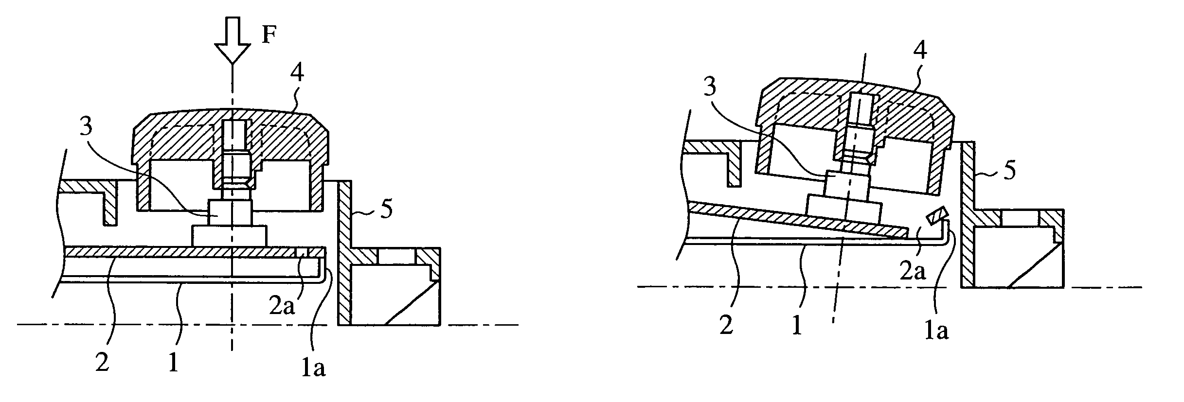
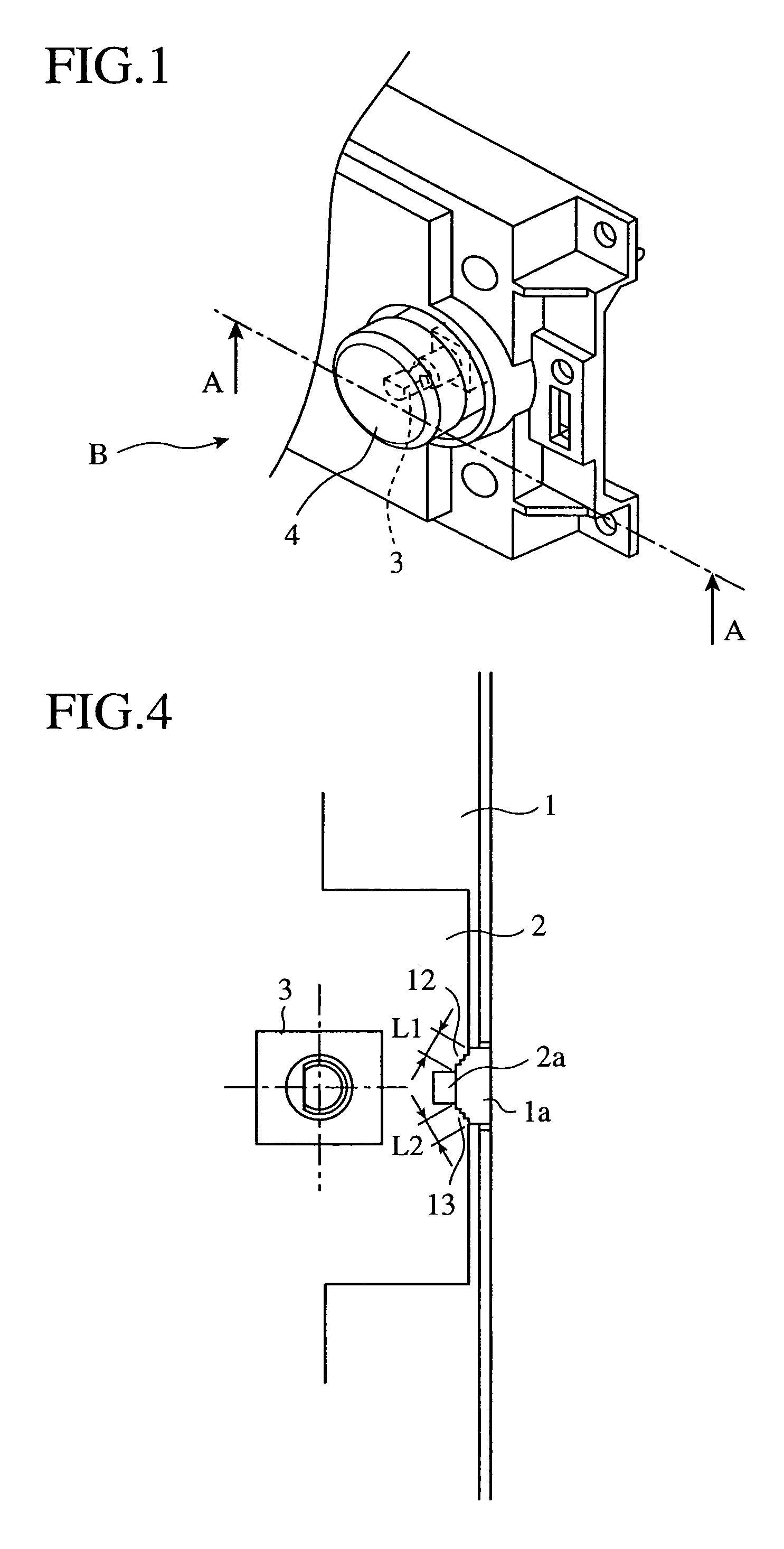
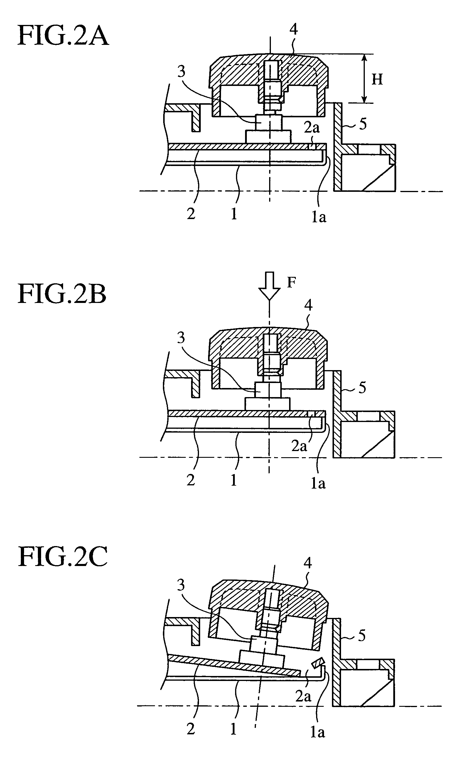
[0020]FIG. 1 is a partially perspective view of an operating knob area in a vehicle audio that is an example of an electronic apparatus according to a first embodiment in the present invention. FIGS. 2A–2C are sectional views taken along the line A—A in FIG. 1 for explanation of a rupturing process of a printed wiring board 2 of the electronic apparatus. FIG. 3A is an elevation view of an essential part of the printed wiring board 2 as seen from the direction of B in FIG. 1 for explanation of an example of modes of rupture of the printed wiring board 2. FIGS. 3B and 3C are schematic side elevation views of the essential part thereof taken along the lines C—C and D—D in FIG. 3A, respectively. FIG. 4 is an elevation view of an essential part of the printed wiring board 2 for explanation of an example of the modes of rupture in the printed wiring board, other than that shown in FIGS. 3A–3C.
[0021]Referring to FIG. 1 to FIG. 4, a chassis 1 supports a printed wiring board 2, and a slit-sh...
second embodiment
[0049]FIGS. 5A–5C are partial sectional views of an operating knob area in a vehicle audio as an example of an electronic apparatus according to a second embodiment in the present invention, corresponding to the aforementioned FIGS. 2A–2C, respectively, and FIG. 5D is a partially enlarged view of a C area in FIG. 5A.
[0050]In FIGS. 5A–5D, the same parts as the ones in FIGS. 2A–2C are designated by similar numerals.
[0051]The electronic apparatus as shown in FIGS. 5A–5D is different from the one as shown in FIGS. 2A–2C in that a light guiding plate 6 for guiding the light emitted from a light source to the front side of a panel 5 is provided and secured within the panel 5 as shown in the figures.
[0052]As shown in FIG. 5D, an engaging portion 6a of the light guiding plate 6 engages an engaging cavity 5a of the panel 5, thereby fixing the light guiding plate 6 within the panel 5 separately from the printed wiring board 2.
[0053]Moreover, as shown in FIG. 5A, a space 7 is prepared in the l...
PUM
 Abstract
Description
Claims
Application Information
 - R&D
- Intellectual Property
- Life Sciences
- Materials
- Tech Scout
- Unparalleled Data Quality
- Higher Quality Content
- 60% Fewer Hallucinations
Browse by: Latest US Patents, China's latest patents, Technical Efficacy Thesaurus, Application Domain, Technology Topic, Popular Technical Reports.
© 2025 PatSnap. All rights reserved.Legal|Privacy policy|Modern Slavery Act Transparency Statement|Sitemap|About US| Contact US: help@patsnap.com


