High-frequency superimposing method and optical disk apparatus using it

a technology of optical disk and superimposed method, which is applied in the field of high-frequency superimposing method and optical disk apparatus using it, can solve problems such as increasing the significance of problems, and achieve the effect of reducing nois

Active Publication Date: 2006-05-02
HITACHI-LG DATA STORAGE +1
View PDF18 Cites 11 Cited by
  • Summary
  • Abstract
  • Description
  • Claims
  • Application Information

AI Technical Summary

Benefits of technology

[0009]As described above, it has been a conventional practice to superimpose a high-frequency component on a semiconductor laser drive current to reduce noise caused by optical feedback.
[0011]In an optical disk drive using a method of reducing noise of optical feedback by superimposing a high-frequency component, it is an object of the present invention to provide a recording method and an optical disk drive which can reduce adverse effects of high-frequency components during data recording.

Problems solved by technology

This problem becomes more significant as pit miniaturization proceeds to meet requirements for higher recording density of the recordable optical disks or as the recording speed increases.

Method used


Image

  • High-frequency superimposing method and optical disk apparatus using it
  • High-frequency superimposing method and optical disk apparatus using it
  • High-frequency superimposing method and optical disk apparatus using it

Examples


embodiment 1

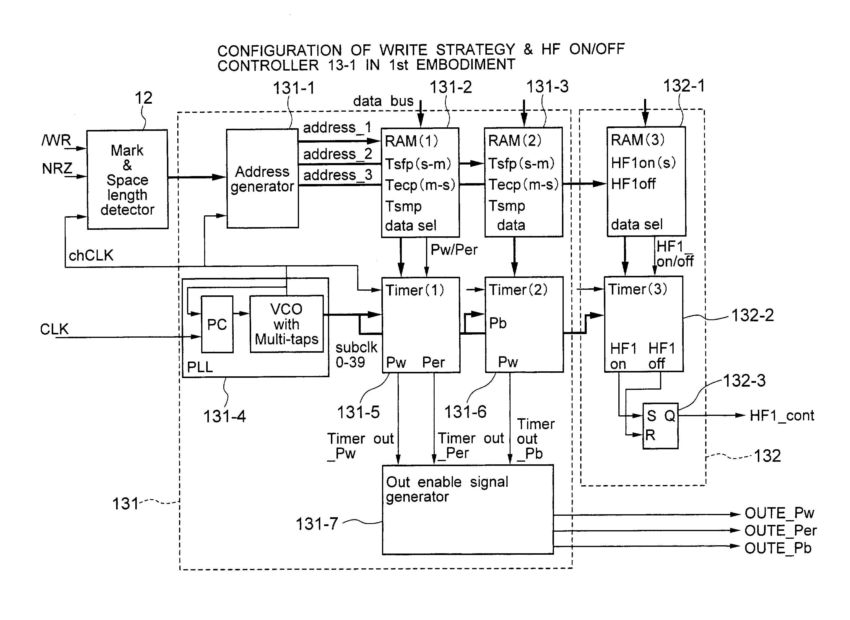
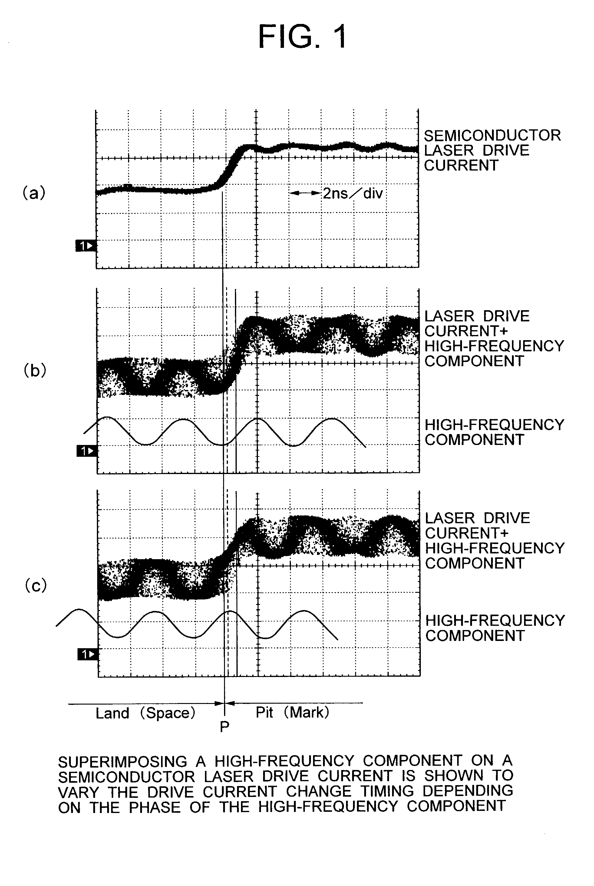
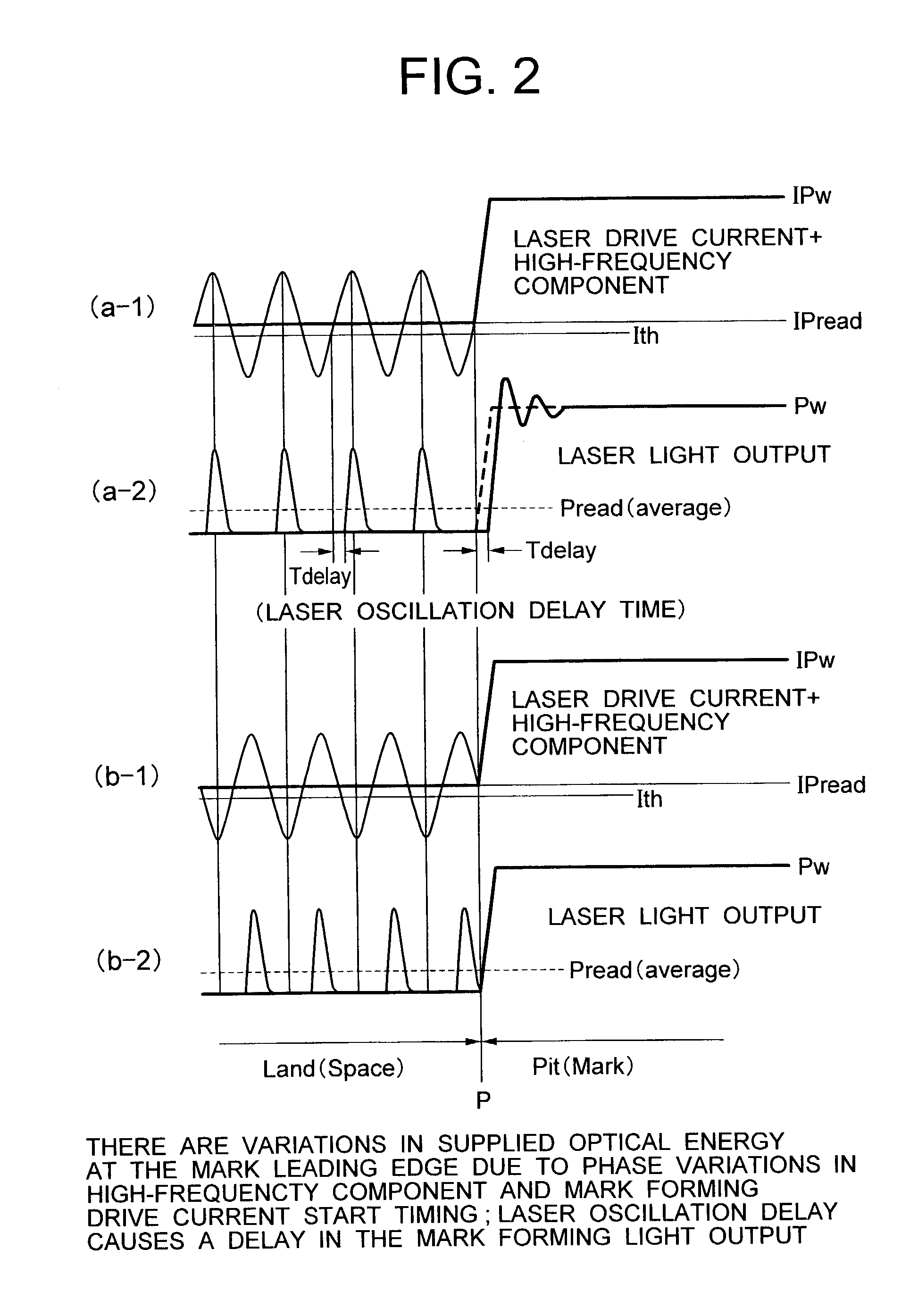
[0058]A first embodiment presents an example in which a high-frequency component is superimposed on a space duration during recording by a first high frequency superimposition control circuit (HF on / off control circuit) which controls an operation of starting and stopping superimposition of a high-frequency component. In this embodiment the recording of CD-R, for example, is contemplated.

[0059]FIG. 4 shows a configuration of the first embodiment. Reference numeral 1 represents a controller (DSP), 2 a flexible cable, and 3-1 a semiconductor laser drive circuit incorporating a write strategy. Denoted 4 is a semiconductor laser diode, 5 a front monitor light receiving element for monitoring an output power of the semiconductor laser diode, 6 a current-voltage conversion circuit for converting an output current of the front monitor light receiving element 5 into a voltage, 7 a sample / hold circuit for sampling and holding an output of the current-voltage conversion circuit 6 at a predete...

embodiment 2

[0107]A second embodiment represents a case where a high-frequency component is superimposed in space and mark periods during recording. More specifically, the second embodiment controls the start and stop of the superimposition of a high-frequency component in space periods using a first high frequency superimposition control circuit and also controls the start and stop of the superimposition of a high-frequency component in mark periods using a second high frequency superimposition control circuit. Example cases of this embodiment include one in which a CD-R is contemplated to be recorded and played back by superimposing a high-frequency component during space periods and a different high-frequency component during mark periods, and one in which a CD-RW is contemplated to be played back by superimposing a high-frequency component and recorded by superimposing another high-frequency component with different frequency and amplitude in space periods.

[0108]FIG. 10 shows a configuratio...

embodiment 3

[0137]A third embodiment is characterized in that a high-frequency component is generated by multiplying the clock CLK supplied from the controller and is synchronized with the recording clock and that a multiplier N and a duty of the high-frequency component signal are varied to realize an optimum high frequency superimposition condition.

[0138]FIG. 16 shows a configuration of the third embodiment. Elements having identical functions with those of the first and second embodiments are given like reference numbers. What differs from the second embodiment is that the internal configuration of the high-frequency component generation circuit (HFM) has been modified (described later). Another difference is that a dividing N1 register 22-1 for setting a first multiplier N1, a dividing N2 register 22-2 for setting a second multiplier N2, and a switching circuit 25 for selecting one of outputs from these registers are added. Still another difference is that a Duty1 register 23-1 for setting ...


PUM

PropertyMeasurementUnit
clock frequenciesaaaaaaaaaa
oscillation delay timeaaaaaaaaaa

Abstract

An optical disk drive includes drive current generation unit for supplying a mark forming semiconductor laser drive current and a space forming semiconductor laser drive current; first high-frequency superimposition unit for superimposing a high-frequency component on the space forming semiconductor laser drive current; and high-frequency superimposition control unit for controlling the first high-frequency superimposition unit to stop the superimposition of the high-frequency component for a predetermined duration prior to a timing at which to switch from the space forming semiconductor laser drive current to the mark forming semiconductor laser drive current, eliminating positional variations on the disk of the mark leading and trailing edges due to the high frequency superimposition.

Description

BACKGROUND OF THE INVENTION[0001]1. Field of the Invention[0002]The present invention relates to a high-frequency superimposing method for superimposing a high-frequency component on a semiconductor laser drive current when recording information on an optical disk in an optical disk drive and to an optical disk drive using the high-frequency superimposing method. More specifically, the present invention relates to a high-frequency superimposing method capable of high-speed, high-density recording and an optical disk drive using the same.[0003]2. Description of the Related Art[0004]Among recordable optical disks there are write-once type optical disks that allow the user to record data only once (e.g., CD-R and DVD-R) and rewritable type optical disks that permit rewriting a number of times (e.g., CD-RW and DVD-RW).[0005]To start recording data, the optical disk drive needs to position its optical head at a desired track (groove) on a disk and start recording from a desired position ...

Claims


Application Information

Patent Timeline
Patent Type & Authority Patents(United States)
IPC IPC(8): G11B7/0045G11B7/00G11B7/004G11B7/006G11B7/125G11B20/12
CPCG11B7/0062G11B7/126G11B20/1217G11B7/1263G11B7/00456G11B2020/1298G11B2007/0006G11B7/004
Inventor ASADA, AKIHIROKUREBAYASHI, MASAAKI
Owner HITACHI-LG DATA STORAGE
Why Eureka
Try Eureka