Optical switch

Inactive Publication Date: 2006-05-02
LUMENTUM OPERATIONS LLC
View PDF30 Cites 22 Cited by
  • Summary
  • Abstract
  • Description
  • Claims
  • Application Information

AI Technical Summary

Benefits of technology

[0015]It is a further object to provide a switch with improved spatial efficiency in order

Problems solved by technology

A “Z-shape” arrangement of optical components is not spatially efficient.
It is apparent that this is not an efficient design since physical size requirements are not optimized in such an “off-axis” design.

Method used


Image

  • Optical switch
  • Optical switch
  • Optical switch

Examples


Embodiment Construction

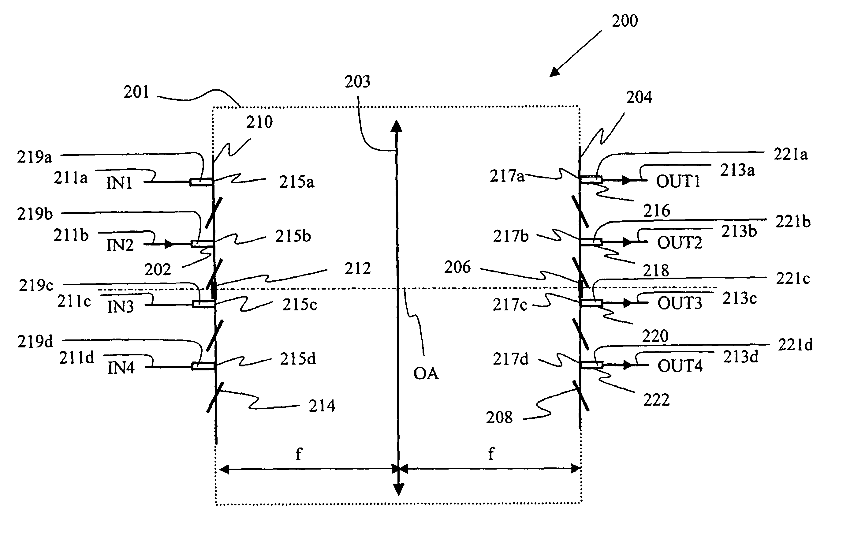
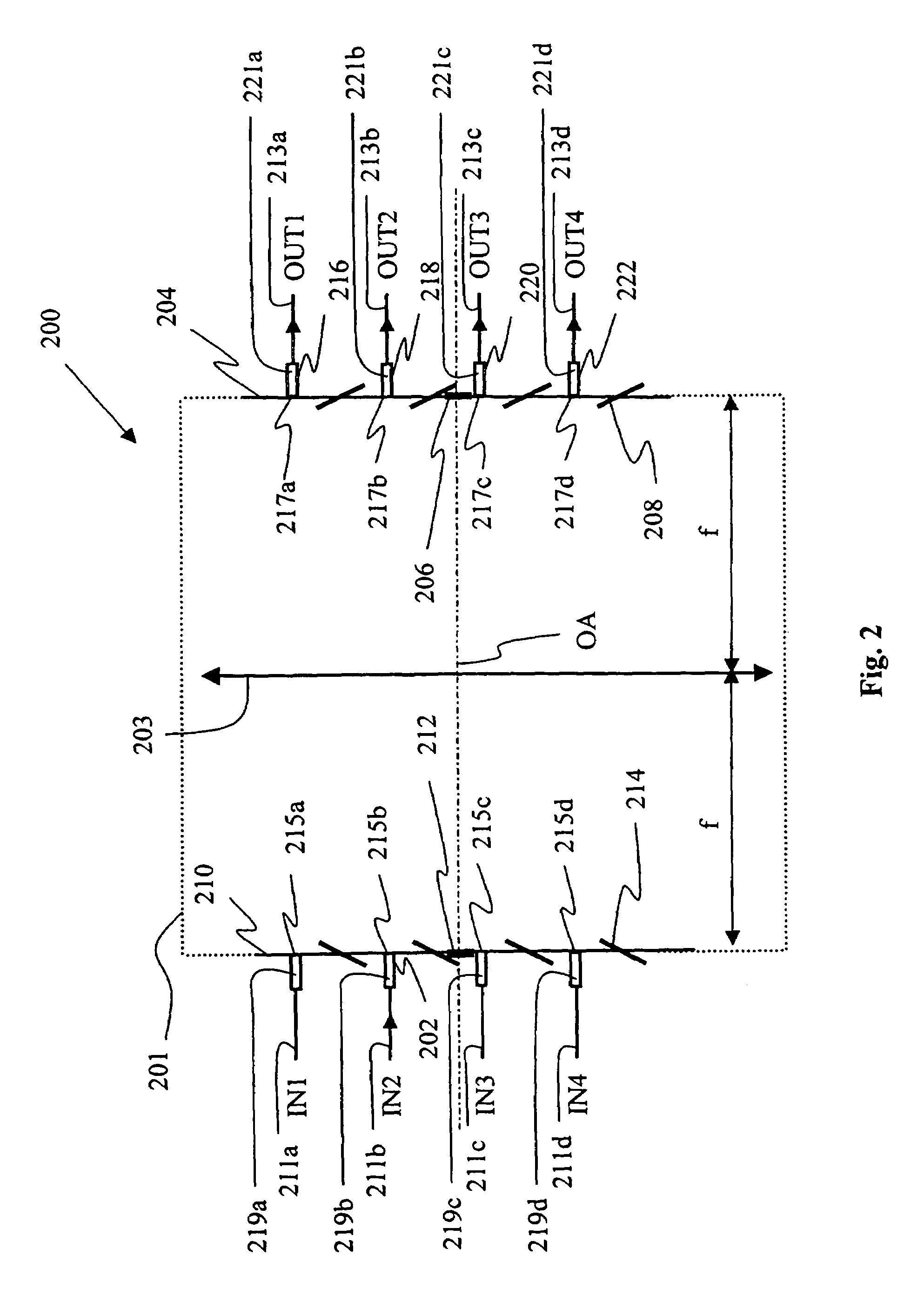
[0046]The present invention develops the optical architecture of large optical cross-connect structures and applies it to medium and small-scale switches to provide a very compact optical switch. For this purpose, two opposing arrays of deflectors, including a plurality of independently and two-dimensionally tiltable micro-mirrors disposed on a MEMS chip, are used in conjunction with an angle-to-offset (ATO) element to provide a switch core in a miniaturized space. The waveguides or fibers are fed through the MEMS chip themselves for compactness, while a single common fixed mirror is added on each opposite MEMS chip for targeting purpose.

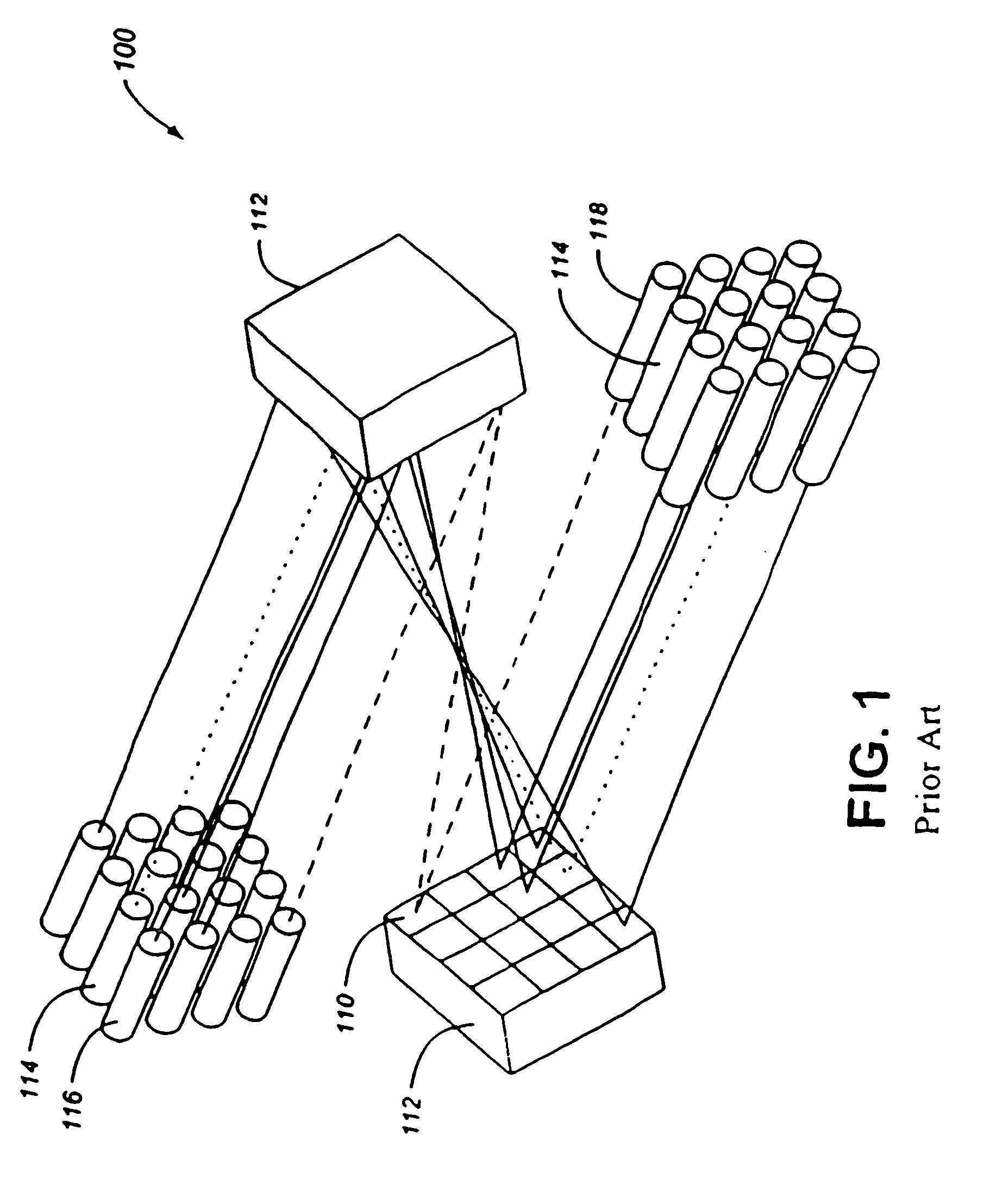
[0047]Prior art deflection means in transmission are accomplished using a dual mirror arrangement for doubly deflecting the beam. For example, an array of 2 mirrors is used to steer the beam in transmission; a first fixed mirror is used to redirect a beam to a second 2D tiltable mirror that provides the beam steering. Such a dual mirror arrangement ...


PUM


Abstract

The invention provides an optical switch having a pair of opposed optical arrays, each optical array including a fixed mirror and a plurality of independently tiltable mirrors, at least one input port for launching a beam of light into the optical switch, said input port being disposed within a respective optical array, at least two output ports for selectively receiving a beam of light from an optical path between the at least one input port and a selected one of the at least two output ports, said at least two output ports being disposed within a respective opposed optical array, and an ATO element having optical power disposed between the pair of opposed optical arrays. The pair of opposed optical arrays is disposed in respective focal planes of the ATO element. Preferably, the ATO element has a focal length equal to a Rayleigh range of a beam of light incident thereon.

Description

CROSS-REFERENCE TO RELATED APPLICATIONS[0001]This application is a continuation-in-part of U.S. patent application Ser. No. 09 / 988,538 filed Nov. 20, 2001, now abandoned which claims priority from Canadian Patent Application No. 2,326,362 filed on Nov. 20, 2000, Canadian Patent Application No. 2,327,862 filed on Dec. 6, 2000, and Canadian Patent Application No. 2,328,759 filed on Dec. 19, 2000, which are all incorporated herein by reference.MICROFICHE APPENDIX[0002]Not ApplicableFIELD OF THE INVENTION[0003]The present invention relates to the field of optical switches.BACKGROUND OF THE INVENTION[0004]Optical matrix switches are commonly used in communications systems for transmitting voice, video and data signals. Generally, optical matrix switches include multiple input and output ports, and have the ability to connect, for purposes of signal transfer, any input port to any output port. Preferably, for N×M switching applications, optical matrix switches also enable multiple connect...

Claims


Application Information

Patent Timeline
IPC IPC(8): G02B6/35G02B6/32G02B6/34H04J14/02H04Q11/00
CPCG02B6/29395G02B6/3556H04J14/02H04Q11/0005H04Q2011/0052G02B6/3512G02B6/3562G02B6/359H04Q2011/0015H04Q2011/0024H04Q2011/0026H04Q2011/003H04Q2011/0035H04Q2011/0037H04Q2011/0043G02B6/32
Inventor DUCELLIER, THOMASPOWELL, IANSHAW, STEPHEN DAVID
Owner LUMENTUM OPERATIONS LLC
Why Eureka
Try Eureka