Storage battery

Inactive Publication Date: 2015-04-23
TOYODA GOSEI CO LTD
View PDF0 Cites 7 Cited by
  • Summary
  • Abstract
  • Description
  • Claims
  • Application Information

AI Technical Summary

Benefits of technology

The storage battery described in this patent has a unique design that simplifies the process of assembly and ensures insulation and sealing properties. The battery consists of two cases that are separated from each other, which eliminates the need for separate encapsulation of the battery elements. The design also reduces the number of components needed and simplifies the process of extracting the battery's electrodes. Additionally, the design allows for the electrodes to be placed on the battery case's end, improving space efficiency while also insulating them from each other. Overall, this design provides a simplified and efficient way to assemble a storage battery.

Problems solved by technology

However, for a need of simultaneously ensuring both insulation property between the electrodes and sealing property of the power generation element (sealing of the positive and negative electrode cases) at the caulked part (the part where the positive and negative electrode cases are caulked while sandwiching the gasket (insulating member) therebetween), the caulking processing comes to be difficult one.
Thus, it is more likely that the gasket might be displaced during the caulking processing step, and the insulating distance might become smaller when the cases are highly deformed by the caulking processing.
In addition, if the gasket cannot follow the deformation of the cases in the caulking processing where the metallic cases and the gasket are deformed together, clearance or the like could be created, which could not ensure sufficient sealing properties.
As described above, for the need of simultaneously ensuring insulation property between the electrodes at the part which is the same as the connecting part where the positive and negative electrode cases that constitute the battery case are sealed, the caulking processing comes to be difficult one.

Method used


Image

  • Storage battery
  • Storage battery
  • Storage battery

Examples


Embodiment Construction

[0027]Hereinafter, a description of an embodiment according to the present invention will be provided.

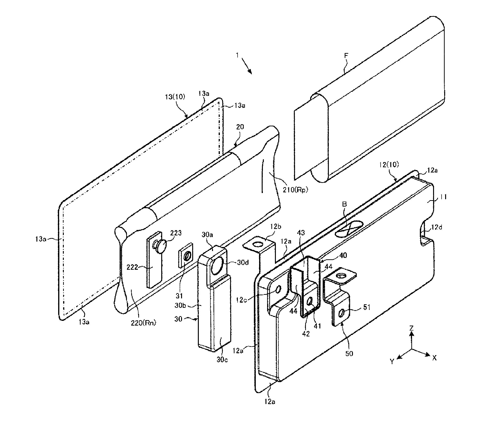
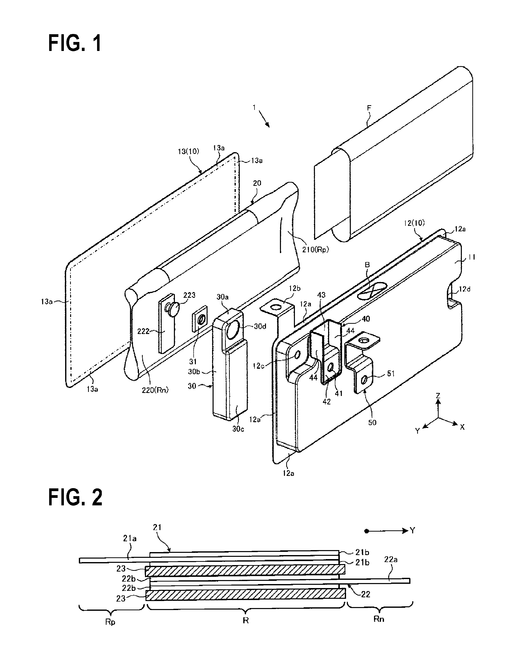
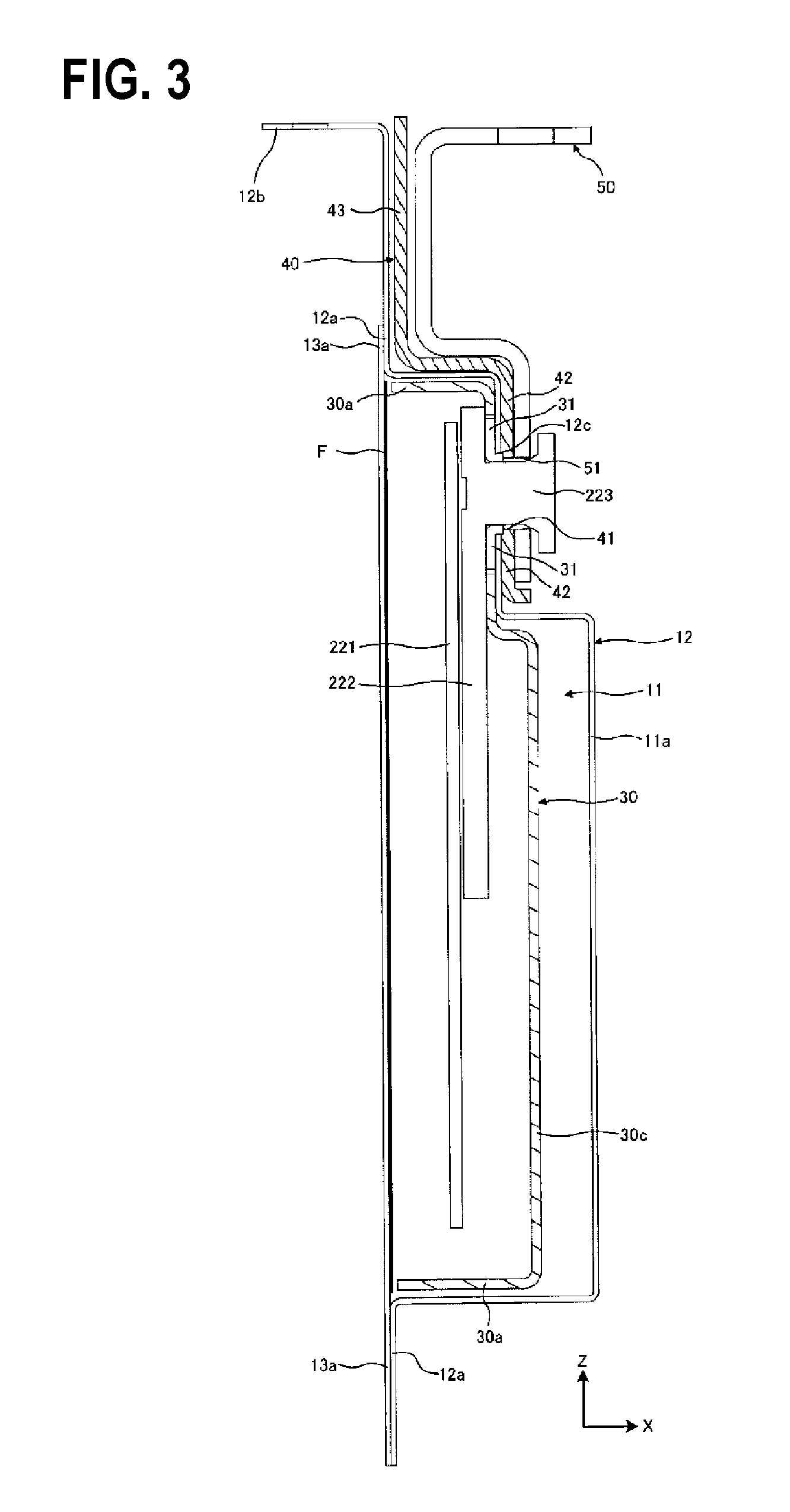
[0028]FIGS. 1 to 6 are views for illustrating the embodiment according to the present invention. FIG. 1 is an exploded perspective view of the configuration of a unit cell. The X-axis, the Y-axis, and the Z-axis define axes that are perpendicular to one another in FIG. 1 and the like. The relation among the X-axis, the Y-axis, and the Z-axis is same in other drawings. The axis corresponding to the vertical direction is defined as the Z-axis in the present embodiment.

[0029]A unit cell (corresponding to a storage battery) 1 according to the present embodiment can be used in an assembled battery that are made of the plurality of unit cells 1 connected in series, and can be used mainly as a secondary battery installed in a hybrid car, an electric car, or the like. Examples of the unit cell 1 include a nickel-hydrogen battery, a lithium-ion secondary battery, and a nickel-cadmium battery...


PUM


Abstract

A storage battery includes a power storage element, a battery case, an internal insulating member, a second electrode terminal, an external insulating member. The power storage element has a stacked structure of a positive plate, a negative plate, and a separator. The battery case includes a first case and a second case that create a space to house the power storage element. The battery case is electrically connected with one electrode of the power storage element and includes a first electrode terminal. The internal insulating member is disposed in the space. The second electrode terminal is connected with the other electrode via the internal insulating member and disposed on a periphery of the battery case at a position different from the connecting part. The external insulating member insulates the second electrode terminal from the battery case.

Description

CROSS-REFERENCE TO RELATED APPLICATIONS[0001]This application claims the benefit of Japanese Patent Application No. 2013-219329 (filed on Oct. 22, 2013), the entire contents of which are incorporated by reference herein.BACKGROUND[0002]1. Technical Field[0003]The present invention relates to a storage battery including a battery case housing a power storage element including a positive electrode body and a negative electrode body that are stacked via a separator.[0004]2. Related Art[0005]For example, the battery described in Patent Literature 1 is made by caulking a metallic positive electrode case and a metallic negative electrode case while sandwiching a resin gasket therebetween and encapsulating a power generation element therein. This type of battery has the merit of the reduced number of constituent members because the battery cases function also as positive and negative electrodes.[0006]PTL 1: JP-A-2000-164259[0007]However, for a need of simultaneously ensuring both insulatio...

Claims


Application Information

Patent Timeline
IPC IPC(8): H01M2/06H01M2/30H01M50/176H01M50/531H01M50/55H01M50/553H01M50/567
CPCH01M2/30H01M2/06H01M50/531H01M50/553H01M50/55H01M50/176H01M50/567Y02E60/10H01M50/545Y02P70/50
Inventor KATAYAMA, JUNTAKIMURA, KENJIUCHIDA, YASUNORIYOKOI, TAKAAKITATSUMI, YOSHIAKI
Owner TOYODA GOSEI CO LTD
Why Eureka
Try Eureka