

Image displaying apparatus and color separating-combining optical system
- Summary
- Abstract
- Description
- Claims
- Application Information
AI Technical Summary
Benefits of technology
Problems solved by technology
Method used
Image

Examples
first embodiment
[0086
[0087]FIG. 3 is a perspective view showing an image displaying apparatus according to the first embodiment of the present invention.
[0088]FIG. 4 is a plan view showing the image displaying apparatus of the first embodiment.
[0089]FIG. 5A is a front view showing the image displaying apparatus of the first embodiment and FIG. 5B is a side view showing the same.
[0090]In FIG. 3, the image displaying apparatus of the first embodiment has upper and lower optical systems arranged in upper and lower layers, respectively. The upper optical system has a light source 101 and a color separating optical system for separating a beam emitted from the light source 101 into color beams.
[0091]The light source 101 provided for the upper optical system of the image displaying apparatus includes a light emitter or a discharge lamp such as an ultra high performance (UHP) mercury lamp, a metal halide lamp, or a xenon lamp and a paraboloidal reflector arranged on the back side of the light emitter. The...
second embodiment
[0178
[0179]An image displaying apparatus according to the second embodiment of the present invention will be explained. Parts and arrangements of the second embodiment other than those explained below are the same as those of the first embodiment, and therefore, the same parts and arrangements are not explained again.
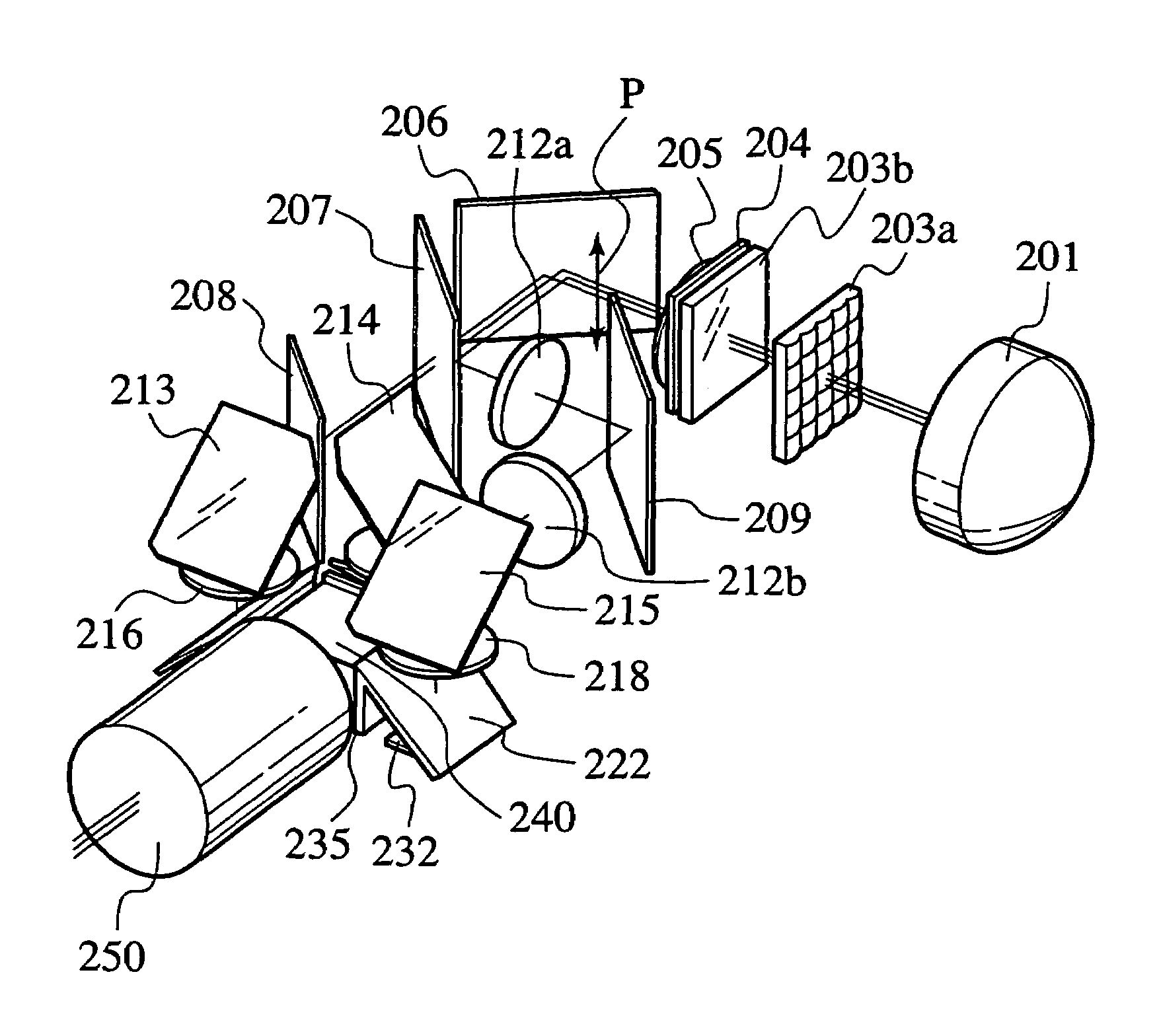
[0180]FIG. 14 is a perspective view showing the image displaying apparatus according to the second embodiment.
[0181]FIG. 15 is a plan view showing the image displaying apparatus of the second embodiment.
[0182]FIG. 16A is a front view showing the image displaying apparatus of the second embodiment, and FIG. 16B is a side view showing the same.
[0183]In FIG. 14, the image displaying apparatus has upper and lower optical systems arranged in two layers. The upper optical system includes a light source 201 and a color separating optical system to separate a beam from the light source 201 into color beams.
[0184]The light source 201 provided for the upper optical system of the ...
third embodiment
[0246
[0247]A color separating-combining optical system according to the third embodiment of the present invention and an image displaying apparatus employing the same will be explained. Parts and arrangements of the third embodiment other than those explained below are the same as those of the first embodiment, and therefore, the same parts and arrangements are not explained again.
[0248]FIG. 20 is a plan view showing the image displaying apparatus employing the color separating-combining optical system according to the third embodiment.
[0249]In FIG. 20, optical elements of the color separating-combining optical system are arranged in a single layer. The color separating optical system separates a beam from a light source 301 into color beams.
[0250]The light source 301 includes a light emitter or a discharge lamp such as an ultra high performance (UHP) mercury lamp, metal halide lamp, or xenon lamp and a paraboloidal reflector arranged on the back side of the light emitter. The light...
PUM
 Abstract
Description
Claims
Application Information